Laser Woodworking Machine

a laser woodworking machine and laser cutting technology, applied in the field of woodworking, can solve the problems of cumbersome use, difficult or straightforward use, and high space requirements of traditional power tools for woodworking, and achieve the effect of reasonable space requirements and improving the safety environment for users

Inactive Publication Date: 2012-02-16
HENDERSON CHARLES L
View PDF6 Cites 11 Cited by
  • Summary
  • Abstract
  • Description
  • Claims
  • Application Information

AI Technical Summary

Benefits of technology

The technical effect of this patent is to provide an inexpensive tool with limited space needs for various wood working tasks which can improve safety conditions for users.

Problems solved by technology

The technical problem addressed in this patent text is the lack of affordable and portable devices designed specifically for woodworking tasks. Current options such as traditional power tools and laser cutting tools are either unsafe or difficult to use, making them unappealing for hobbyists and DIYers. There is a need for a small, safe, and efficient tool that can improve both safety and usability for various woodworking applications.

Method used


Image

  • Laser Woodworking Machine
  • Laser Woodworking Machine
  • Laser Woodworking Machine

Examples


Embodiment Construction

[0027]A machine for laser woodworking is disclosed. The machine provides precise woodcuts via a directed laser beam.

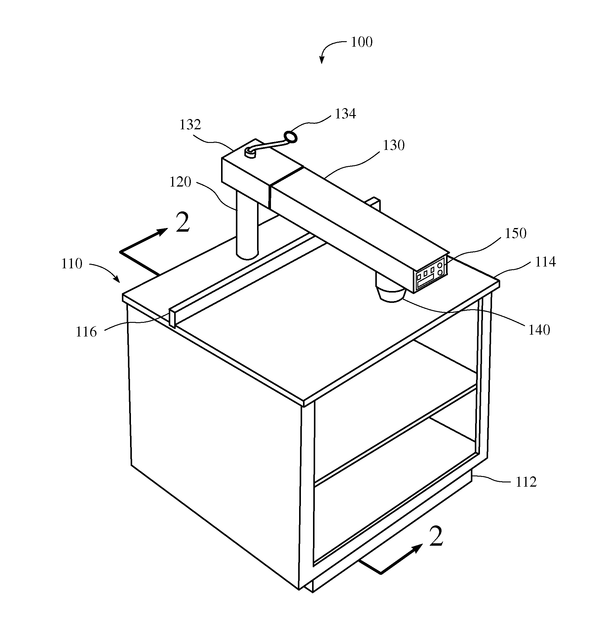
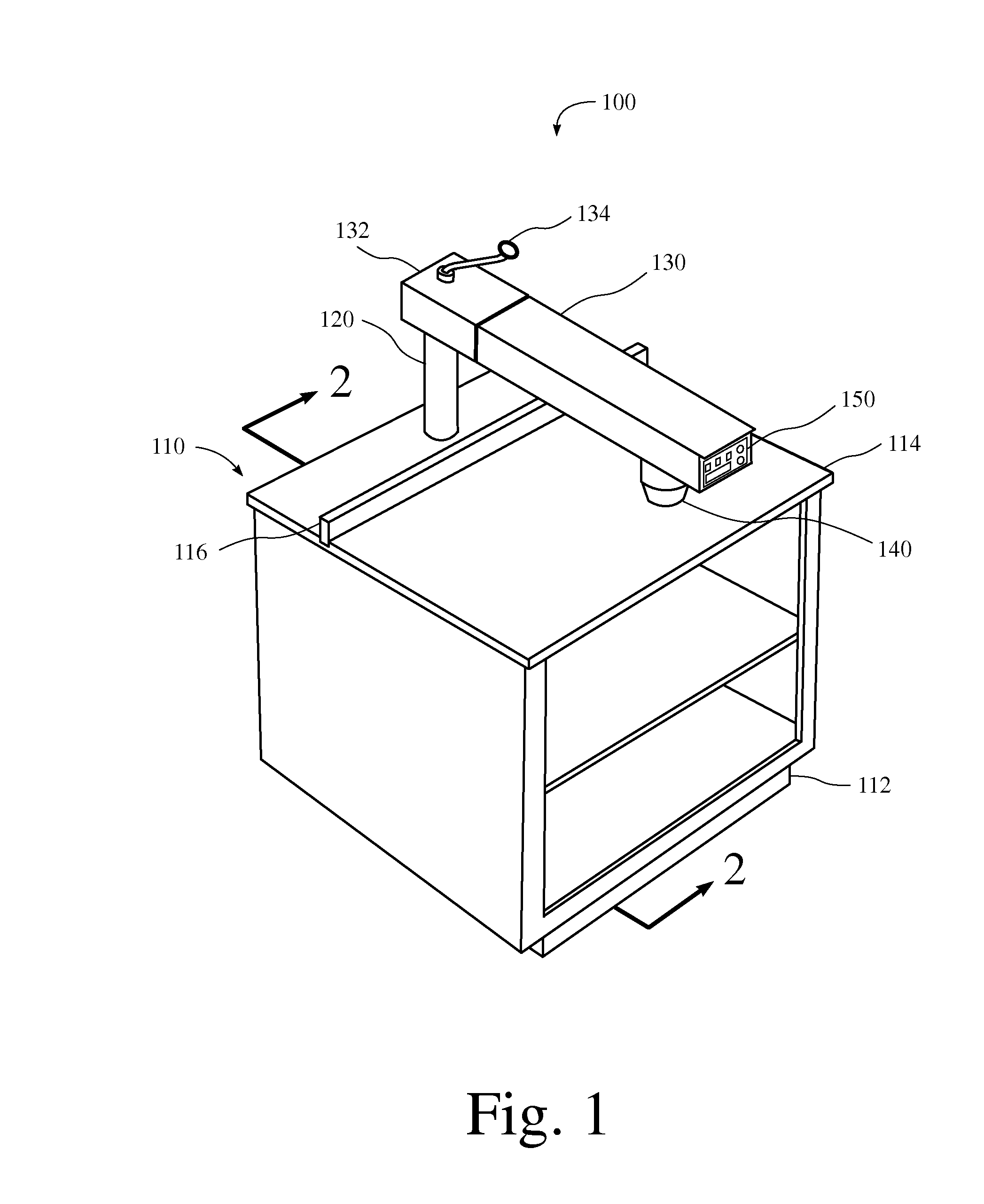
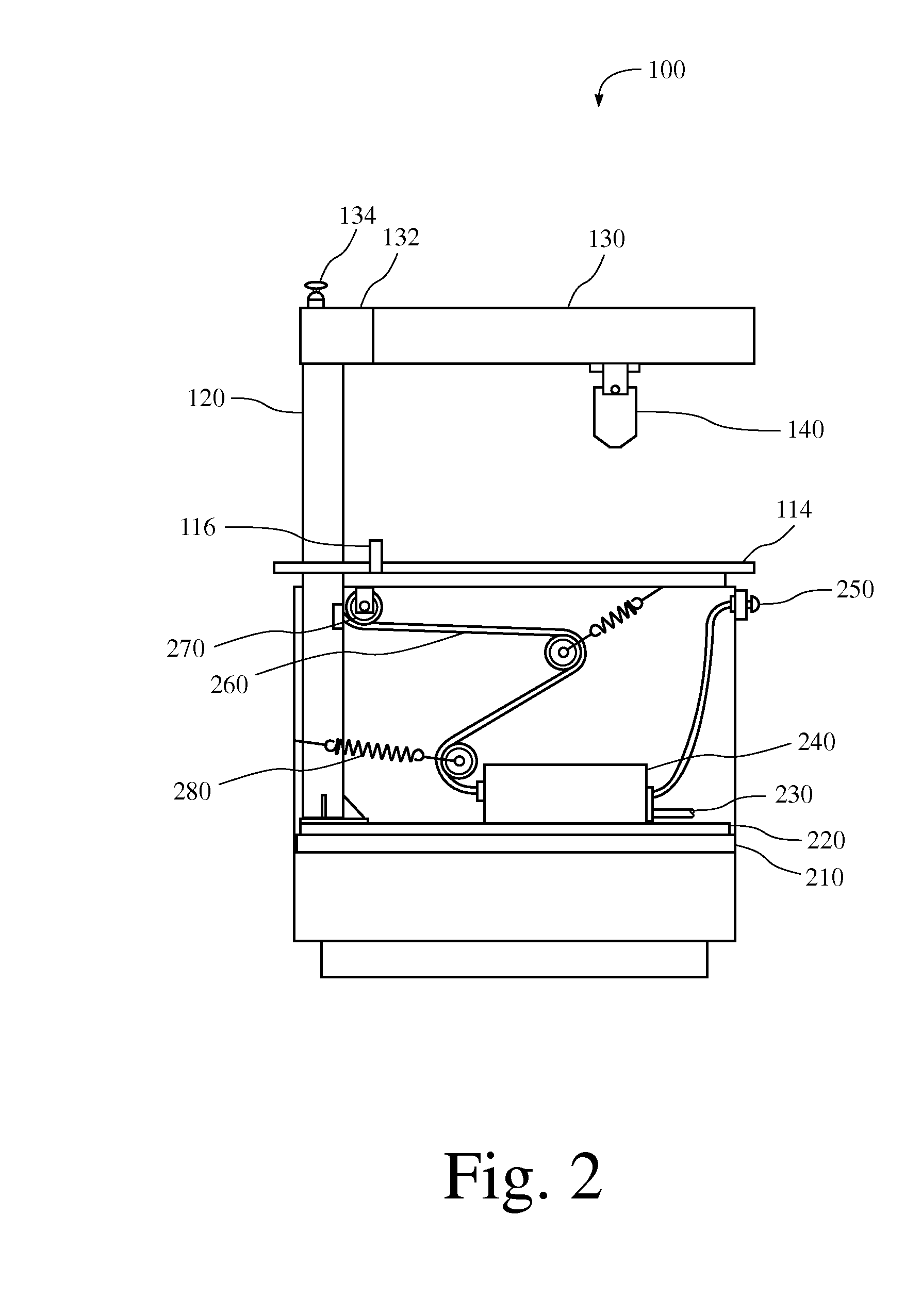
[0028]FIG. 1 is a perspective view of one embodiment of a laser woodworking machine 100. The laser woodworking machine 100 includes a cabinet enclosure 110, a cabinet base 112, a support column 120, a radial arm 130, a laser head 140, and a control panel 150. The cabinet enclosure 110 typically also includes doors (not shown) or the like for enclosing the front of the cabinet enclosure 110 as well as providing access to the inside of the cabinet. In some embodiments, the cabinet enclosure 110 includes an openable and / or detachable panel to cover the front access opening. FIG. 2 is a side view of one embodiment of the laser woodworking machine 100 and also shows the interior of the cabinet enclosure 110.

[0029]The machine 100 is quiet and simple to use while also providing for precise and sanding free woodworking. The laser beam cuts to an exact depth with fine cuts that...


PUM

PropertyMeasurementUnit
Poweraaaaaaaaaa
Depthaaaaaaaaaa
Frequencyaaaaaaaaaa

Abstract

A laser woodworking machine for cutting wood is disclosed. The machine includes a laser cutting head having two sections structurally configured to include sensors for measurements of depth and of reflected frequencies, a laser unit for supplying power to the laser cutting head, a cabinet enclosure for housing the laser unit and including a table surface, a radial arm supported by a column secured to the inside rear portion of the cabinet enclosure and including a pair of radial supports extending perpendicularly from opposite sides of the column and parallel to each other, and a glider carriage secured to the radial supports and including two substantially flat surfaces above and below the radial supports so that the glider carriage slides along the radial supports via sleeves, the glider carriage further comprising support for the laser cutting head so that the laser cutting head is moveable along the radial arm.

Description


Claims


Application Information

Patent Timeline
Owner HENDERSON CHARLES L
Why Eureka
Try Eureka