Vibration control device for beam-and-column frame
Active Publication Date: 2012-02-16
NAGOYA UNIVERSITY +1
View PDF8 Cites 58 Cited by
Summary
Abstract
Description
Claims
Application Information
AI Technical Summary
This helps you quickly interpret patents by identifying the three key elements:
Problems solved by technology
Method used
Benefits of technology
Benefits of technology
[0031]To the damper members, it is even possible to apply squared or angled configurations that approximate a letter-U shape, in addition to the letter-U-shaped configuration. For example, the following are available: a configuration that has an opening at the long-side section in a pentagon with a home-base shaped configuration, a configuration with a letter-V shape, and the like. In this instance, it is possible to demonstrate the advantageous effects sufficiently, although there might arise such a fear that stress concentration occurs at the squared or angled sections forming the apexes of the pentagon or at the corner of the letter-V shape, compared with a letter-U-shaped configuration, when the damper members undergo bending deformations. Note that it is more preferable that the damper members can be formed as a letter-U-shaped configuration, respectively.
[0032]Moreover, in the present invention, it is fine that said damper members can comprise; a first damper member with said letter-U-shaped configuration; and a second damper member being accommodated inside the letter-U shape of the first damper member, and being disposed in a letter-U-shaped configuration so as to open in an identical direction. That is, a dual letter-U-shaped configuration is formed by means of the first damper member and second damper member. By means of this setup, it is possible to further enhance the rigidity for supporting the parallel member, rigidity which results from the damper members. Note that, in a case where it is desired to set up the rigidity for supporting the parallel member higher, it is effective to make the damper members dually, because the rigidity, which results from the damper members, leads to suitably adjusting the aforesaid supporting rigidity.
[0033]In a case where the damper members are thus formed as a dual letter-U-shaped configuration, it is even possible to replace each of the damper members with a letter-U-shaped configuration by those with a polygonal squared or angled configuration, or those with a letter-V-shaped configuration. However, from the viewpoint of stress concentration, forming the damper members as a letter-U-shaped configuration is more preferable than the latter.
[0034]Moreover, in the present invention, it is fine that said parallel member can comprise:
[0035]a parallel flat plate being disposed to parallelly face with respect to said first member and separate away therefrom; and
[0036]at least one rib-shaped member being disposed upright on one of the sides of said parallel flat plate adjacent to a side of said second member so as to extend in a direction that crosses a rotational axis of said rotary supporting member orthogonally; and
Problems solved by technology
Therefore, there is such a problem that the cross section of the braces should be enlarged.
However, it is difficult to produce only shear deformations in the plastic body by this constitution, and so the load-deformation characteristic (e.g., the Q-δ characteristic) at the time of applying repetitive loads horizontally thereto becomes a slippage type (being also referred to as a non-spindle type, or a non-complete elasto-plasticity type, in general).
That is, in the constitution according to FIG. 1 of Patent Literature No. 1, even if it is possible not to make any compression forces act on the braces, the restorability is not favorable because the load-deformation characteristic becomes a slippage type when the plastic body undergoes, in addition to shear deformations, deformations as well in the axial directions of the braces in which tensile forces act.
That is, in the same manner as the constitution according to FIG. 2 of Patent Literature No. 1, the constitution being set forth in Patent Literature No. 2 has such a problem that the cross section of the braces should be enlarged.
This fear makes one of the causes that the vibration control device declines in the durability.
This problem not only arises from the constitutions of the fixed plate and movable plate themselves, namely, their small rigidities against the deformations in the normal direction with respect to a plane of the beam-and-column frame, but also arises from the tensile forces and compression forces that act on the braces (5, 6) alternately.Patent Literature No. 1: Japanese Unexamined Patent Publication (KOKAI) Gazette No. 2003-90,144; andPatent Literature No. 2: Japanese Unexamined Patent Publication (KOKAI) Gazette No. 2006-152,722
Method used
Image
Click on the blue label to locate the original text in one second.
Reading with bidirectional positioning of images and text.
[0102]Next, explanations will be made on modified modes of the vibration control device for beam-and-column frame according to the First Embodiment Mode, namely, on two types of them, for instance. Specifically, only the paired damper members (80, 90) are altered.
[0103]In FIG. 7(a), a pair of damper members (180, 190) serving as a First Modified Mode are illustrated. These paired damper members (180, 190) are formed as a letter-U-shaped configuration that opens toward the opposite sides to the rotary supporting member 40, respectively. That is, although the aforesaid paired dampers (180, 190) are formed as the same configuration as that of the damper members (80, 90) according to the First Embodiment Mode, but differ from them in the installation directions.
[0104]In this instance as well, the same advantages as those of the First Embodiment Mode can be effected virtually. However, since the supporting rigidity and yield points of the damper mem...
second embodiment
Mode
[0106]Next, explanations will be made on a vibration control device for beam-and-column frame according to a Second Embodiment Mode with reference to FIG. 8 through FIG. 10. The vibration control device for beam-and-column frame according to the Second Embodiment Mode comprises an installation plate 20, a parallel member 330, a rotary supporting member 340, first and second gasset plates (51, 52), a first brace 360, a second brace 370, and a pair of damper members (80, 90). Here, the aforesaid vibration control device according to the Second Embodiment Mode is installed to a beam-and-column frame in a state of being inverted upside down, with respect to the vibration control device according to the First Embodiment Mode. Hereinafter, explanations will be made only on constitutions of the vibration control device according to the Second Embodiment Mode alone that are distinct from those of the vibration control device according to the First Embodiment Mode.
[0107]The parallel memb...
PUM
Abstract
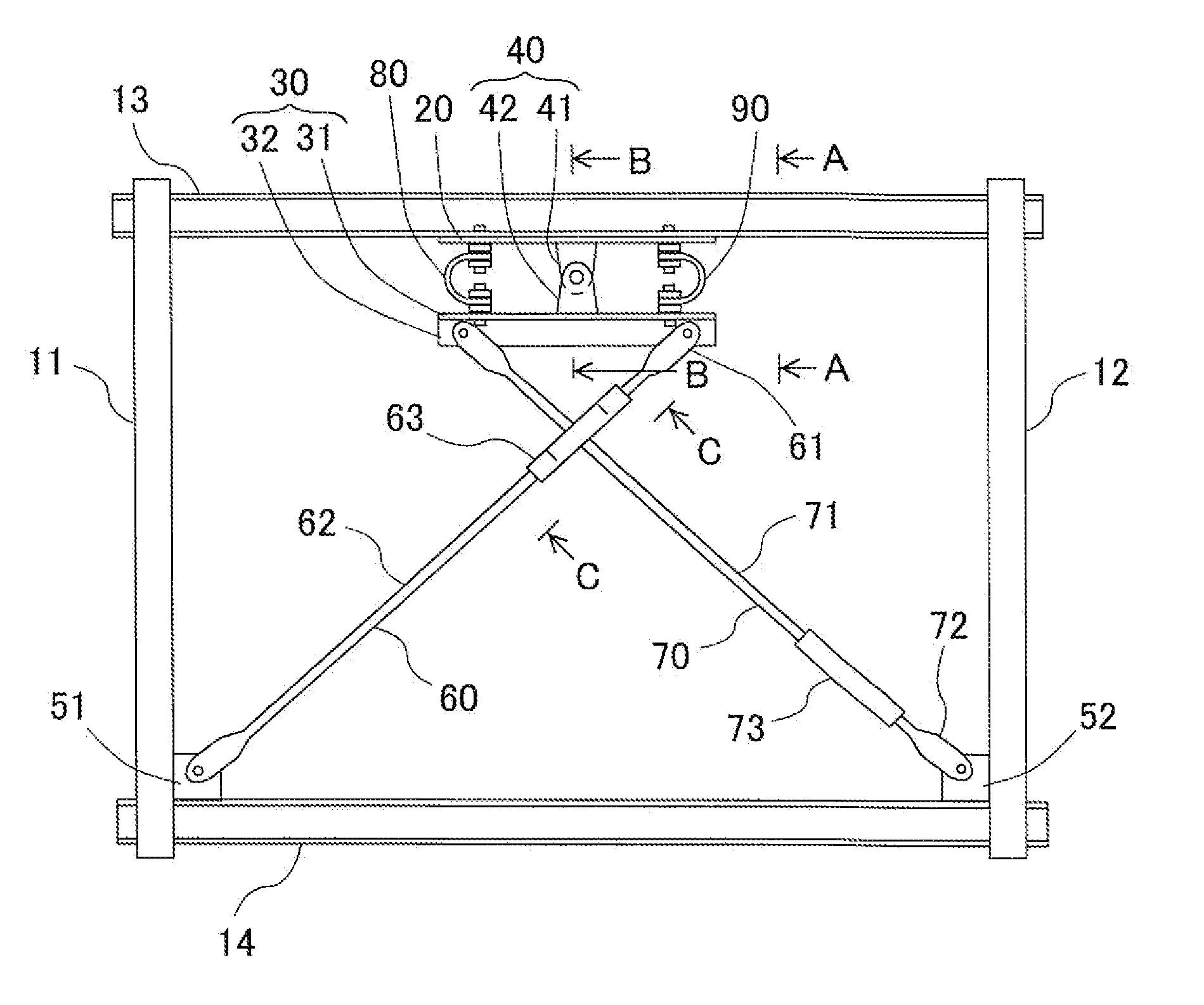
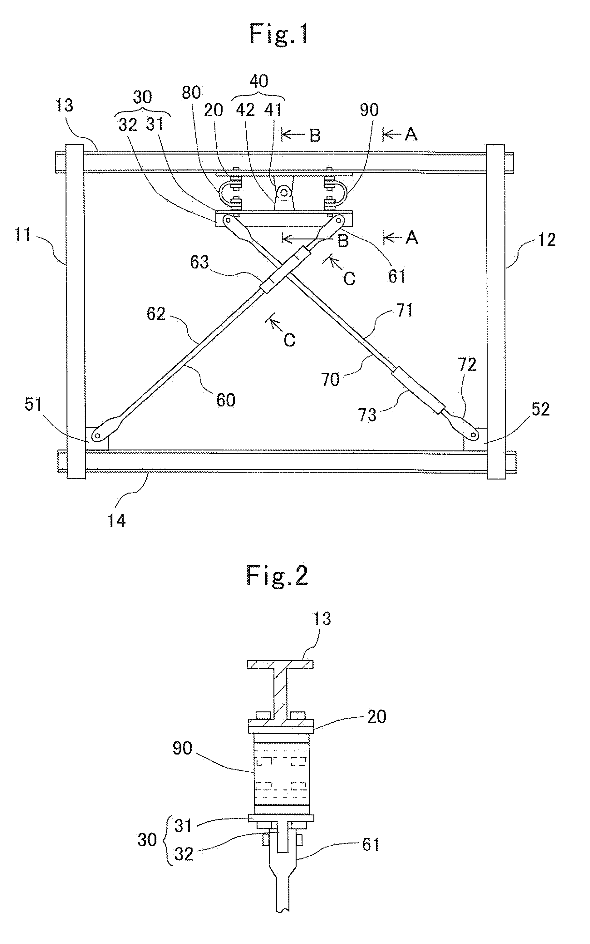
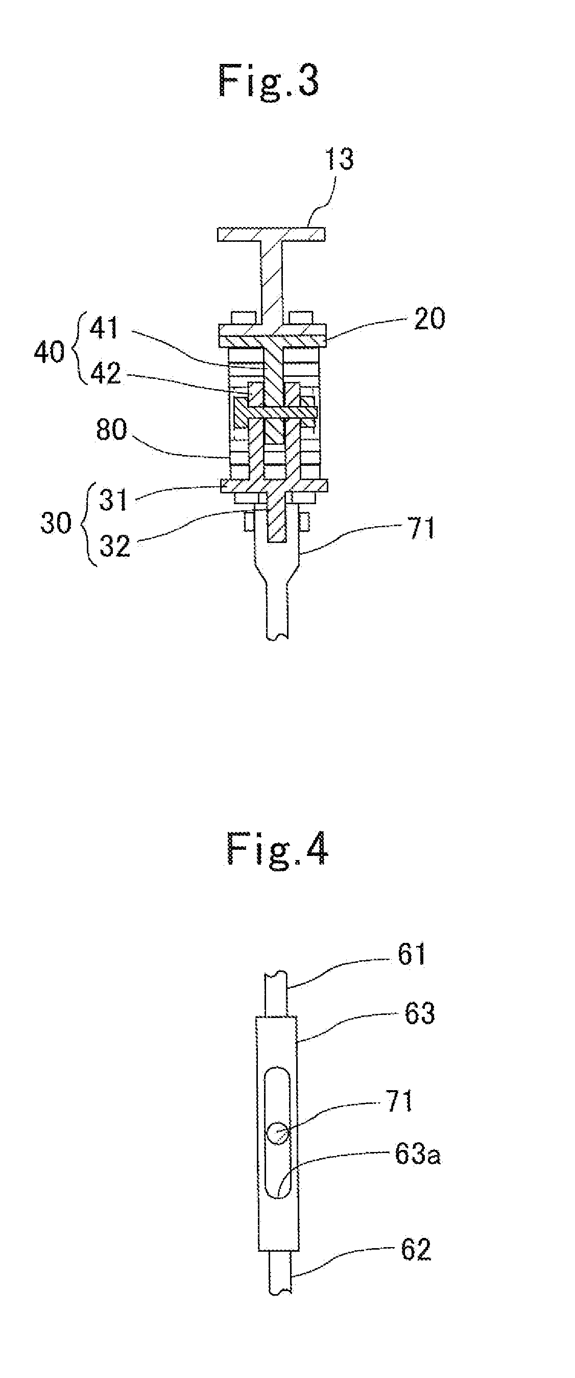
To set up such a constitution that no compression forces act on braces, alternatively, to set up a constitution that makes it possible to make compression forces to be applied to braces smaller extremely; and to provide a vibration control device for beam-and-column frame that can demonstrate high vibration control performance.A rotary supporting member 40 supports a parallel member 30 rotatably with respect to an upper beam 13. A first brace 60 connects an opposite-end side of the parallel member 30 with an opposite-end side of a lower beam 14. A second brace 70 connects another opposite-end side of the parallel member 30 with another opposite-end side of the lower beam 14. An intersection position of the first brace 60 with the second brace 70 is positioned more adjacent to a side of the upper beam 13 than where an intermediate position between the upper beam 13 and the lower beam 14 is present. The resulting vibration control device includes damper members (80, 90) being disposed respectively so as to be interposed between the parallel member 30 and the upper beam 13, connecting the parallel member 30 with the upper beam 13, and being disposed to make a pair at least on both sides each of which is separated away from the rotary supporting member 40 to interpose the rotary supporting member 40 therebetween.
Description
TECHNICAL FIELD[0001]The present invention is one which relates to a vibration control device for beam-and-column frame.BACKGROUND ART[0002]As a vibration control device for beam-and-column frame, one which is set forth in Japanese Unexamined Patent Publication (KOKAI) Gazette No. 2003-90,144 (or Patent Literature No. 1) has been heretofore available conventionally. The vibration control device illustrated in FIG. 2 of Patent Literature No. 1 comprises a plastic body being fixed to an upper beam, and a pair of braces connecting this plastic body with a lower beam. That is, it is possible to absorb seismic energies because the plastic body deforms in a case where a beam-and-column frame has deformed horizontally; as a result, it is one which can keep the beam-and-column frame from vibrating.[0003]However, in the constitution according to FIG. 2 of Patent Literature No. 1, one of the braces undergoes tensile deformations, but the other one of the braces undergoes compression deformati...
Claims
Application Information
Patent Timeline
Application Date:The date an application was filed.
Publication Date:The date a patent or application was officially published.
First Publication Date:The earliest publication date of a patent with the same application number.
Issue Date:Publication date of the patent grant document.
PCT Entry Date:The Entry date of PCT National Phase.
Estimated Expiry Date:The statutory expiry date of a patent right according to the Patent Law, and it is the longest term of protection that the patent right can achieve without the termination of the patent right due to other reasons(Term extension factor has been taken into account ).
Invalid Date:Actual expiry date is based on effective date or publication date of legal transaction data of invalid patent.

