Methods and apparatuses for clock domain crossing

Active Publication Date: 2012-02-16
INTEGRATED DEVICE TECH INC
View PDF2 Cites 2 Cited by
  • Summary
  • Abstract
  • Description
  • Claims
  • Application Information

AI Technical Summary

Benefits of technology

[0014]FIG. 4 is a simplified block diagram illustrating a sample generator according to one or more embodiments of the present invention;
[0015]FIG. 5 is a simplified block diagram illustrating a differentiator according to one or more embodiments of the present invention;
[0016]FIG. 6 illustrates waveforms for a first data type generated by various stages of one or more embodiments of the present invention;
[0017]FIG. 7 illustrates waveforms for a second data type generated by various stages of one or more embodiments of the present invention; and
[0018]FIG. 8 illustrates waveforms for a third data type generated by various stages of one or more embodiments of the present invention.
[0019]In the following description, elements, circuits, and functions may be shown in block diagram form in

Problems solved by technology

A delay circuit generates the time delay.

Method used


Image

  • Methods and apparatuses for clock domain crossing
  • Methods and apparatuses for clock domain crossing
  • Methods and apparatuses for clock domain crossing

Examples


Embodiment Construction

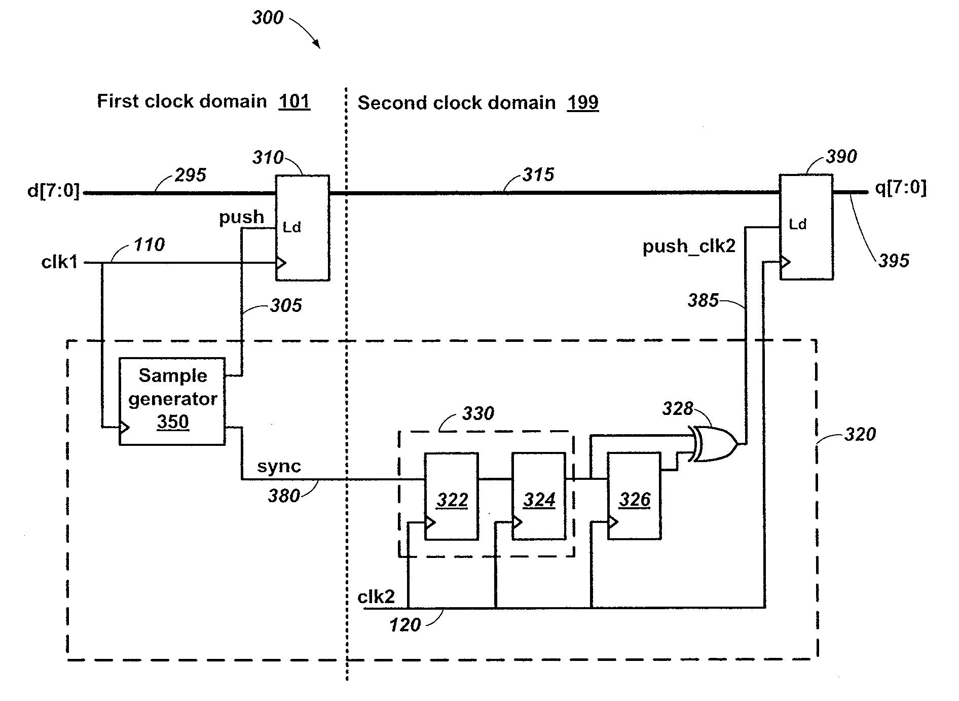
[0019]In the following description, elements, circuits, and functions may be shown in block diagram form in order not to obscure the present invention in unnecessary detail. Conversely, specific implementations shown and described are exemplary only and should not be construed as the only way to implement the present invention unless specified otherwise herein. Additionally, block definitions and partitioning of logic between various blocks is exemplary of a specific implementation. It will be readily apparent to one of ordinary skill in the art that the present invention may be practiced by numerous other partitioning solutions. For the most part, details concerning timing considerations and the like have been omitted where such details are not necessary to obtain a complete understanding of the present invention and are within the abilities of persons of ordinary skill in the relevant art.

[0020]Furthermore, in this description of embodiments of the invention, reference is made to ...


PUM


Abstract

Clock-domain-crossing systems and methods include an integrator that accumulates input samples over multiple clock cycles in a first clock domain to generate an accumulation result. Clock-domain-crossing circuitry samples the accumulation result in the first clock domain after each of a repeating accumulation count to generate a first domain accumulation. The first domain accumulation is sampled in a second clock domain after a time delay to generate a second domain accumulation. The time delay ensures proper setup and hold time parameters for the second clock domain relative to the first clock domain. A differentiator generates output information in the second clock domain by delaying the second domain accumulation and subtracting the delayed second domain accumulation from the second domain accumulation. The systems and methods preserve temporal characteristics of the input information in the first clock domain when it is transferred to the second clock domain as the output information.

Description

TECHNICAL FIELD[0001]Embodiments of the present disclosure relate generally to data handling in digital circuits and, more particularly, to methods and apparatuses for passing data across different clock domains.BACKGROUND[0002]In many digital systems, it is sometimes necessary to move signals and signals containing data between different clock domains. These different clock domains may be at completely independent frequencies and phases, different only in frequency, different only in phase, or one clock domain may be derivative of the other clock domain. Problems can occur when moving signals between clock domains. If a flip-flop is clocking in a signal that originated in another clock domain, there may be no way to guarantee the necessary set-up and hold time for the flip-flop. As a result, it may not be possible to determine on which clock edge the flip-flop will detect a transition on the data input. Or, even worse, the flip-flop may become unstable and begin oscillating if the ...

Claims


Application Information

Patent Timeline
IPC IPC(8): H03L7/00
CPCG06F5/06H04L7/0012
InventorSINGHAL, ROHITDEMARCO, CHRIS
OwnerINTEGRATED DEVICE TECH INC