Liquid-crystal display device

a liquid crystal display and display device technology, applied in non-linear optics, instruments, optics, etc., can solve the problems of inability to read markers on the panel, inability to read markers formed in the non-display region, and inability to read markers, so as to minimize the enlargement of the picture frame region of the lcd panel due to markers

Active Publication Date: 2012-02-16
NEC LCD TECH CORP
View PDF1 Cites 5 Cited by
  • Summary
  • Abstract
  • Description
  • Claims
  • Application Information

AI Technical Summary

Benefits of technology

[0020]An object of the present invention is to provide a LCD device that makes it possible to attach an optical element to a LCD panel with high positional accuracy while avoiding or minimizing the enlargement of the picture-frame region (in other words, the non-display region) induced by the formation of markers on the LCD panel and the increase of the fabrication cost, and a method of fabricating the LCD device.
[0048]In another preferred embodiment of the method according to the second aspect of the invention, in the step of forming the markers, at least one of the markers is located on a side or edge of the LCD panel where a liquid-crystal injection hole of the LCD panel is present. In this embodiment, the effect by the enlargement of the picture-frame region of the LCD panel due to the markers can be minimized.

Problems solved by technology

Accordingly, there is a problem that the markers on the panel are unable to be read in the placement or attachment operation of the element to the panel.
Therefore, similar to the LCD device operating in the normally black mode, there is a problem that the markers formed in the non-display region where the alignment films do not exist are unable to be read.
Accordingly, with the reflective type LCD device also, there is a problem that the markers are unable to be read in the attachment operation of the optical element to the panel.
Moreover, with the reflective type LCD device, it is usual that the obtainable contrast due to the reflected light generated by the reflective electrodes is low.
Therefore, there is another problem that the markers cannot be recognized with high accuracy.
Therefore, there is a problem that the distance between the display region and the sealing material for sealing or enclosing the liquid crystal will be enlarged, in other words, the picture-frame region will be widen.
Moreover, since the step or process of accurately deviating the upper and lower polarizer plates 103 and 104 and attaching the same is required, there is another problem that the fabrication cost cannot be lowered.

Method used


Image

  • Liquid-crystal display device
  • Liquid-crystal display device
  • Liquid-crystal display device

Examples


first embodiment

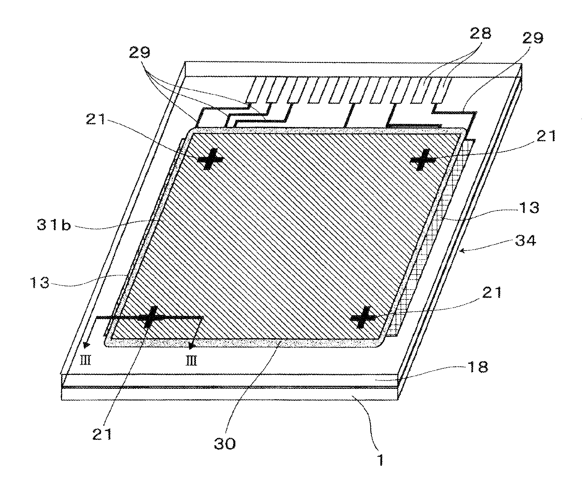
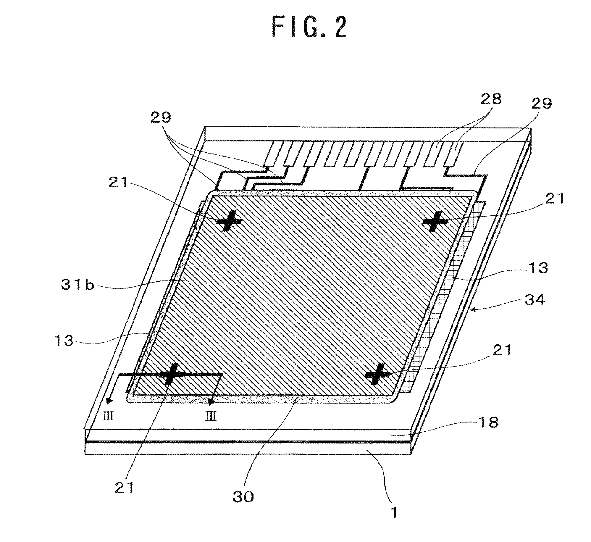
[0071]The schematic structure of a LCD device according to a first embodiment of the present invention is shown in FIGS. 2 and 3, where the LCD device is designed to operate in the normally white mode.

[0072]In FIGS. 2 and 3, the reference numeral 34 denotes a LCD panel incorporated into the LCD device according to the first embodiment of the invention. The LCD panel 34 comprises a driver substrate 1 as a main substrate, an opposite substrate 18 coupled with the driver substrate 1 to be opposite thereto, a liquid crystal 35 (see FIG. 3) enclosed in the gap between the driver and opposite substrates 1 and 18, polarizer plates 31a and 31b attached respectively to the outer surfaces of the driver and opposite substrates 1 and 18, and four markers 21 formed respectively at the positions that overlaps with the polarizer plate 31b on the opposite substrate 18. The markers 21, each of which is made of a material with a light-shielding property (i.e., an opaque material), are used for positi...

second embodiment

[0122]FIGS. 14 and 15 show the LCD panel incorporated into a LCD device according to a second embodiment of the invention. Unlike the above-described first embodiment, this LCD device is designed to operate in the normally black mode. FIG. 14 is a partial cross-sectional view showing the structure of the LCD panel 34 in the vicinity of one of the markers 21, and FIG. 15 is an explanatory partial plan view showing the alignment state of the liquid-crystal molecules in the vicinity of the said marker 21 and the display region. The markers 21 used in the second embodiment are the same as those used in the first embodiment.

[0123]With the LCD device designed to operate in the normally black mode, the markers 21 are unable to be recognized visually even if the alignment direction of the molecules of the liquid crystal 35 in the vicinities of the markers 21 is equalized to that of the molecules of the liquid crystal 35 in the display region. This is because light does not penetrate through...

third embodiment

[0135]FIG. 16 is a partial cross-sectional view of the vicinity of one of the markers 21, which shows the LCD panel 34 incorporated into a LCD device according to a third embodiment of the invention. The markers 21, which are the same as those used in the first embodiment, are located on the inner surface of the opposite substrate 18 (concretely speaking, on the surface of the overcoat film 19). Illustration of the sealing material 30 is omitted in FIG. 16.

[0136]The LCD panel 34 shown in FIG. 16, which is designed to operate in the normally black mode like the above-described second embodiment, comprises pairs of electrodes for applying a voltage to the liquid crystal in the vicinities of the markers 21, in other words, pairs of electrodes for regulating the alignment direction of the liquid-crystal molecules near the markers 21. These pairs of electrodes serve as the alignment direction regulators and therefore, they may be termed “alignment direction regulating electrodes”. Here, ...


PUM

PropertyMeasurementUnit
angleaaaaaaaaaa
voltageaaaaaaaaaa
weightaaaaaaaaaa

Abstract

A liquid-crystal display device makes it possible to attach an optical element to a liquid-crystal display panel with high positional accuracy while avoiding or minimizing the enlargement of the picture-frame region (i.e., the non-display region) induced by the formation of markers on the panel and the increase of the fabrication cost. The panel comprises a main substrate, an opposite substrate, and a liquid crystal enclosed in a gap between the main and opposite substrates, wherein a polarizer plate is attached at least to the opposite substrate. Markers for attaching an optical element to the panel are formed at positions that overlap with the polarizer plate in a non-display region on the main or opposite substrate. Alignment direction regulators regulate the alignment of the liquid crystal molecules to a predetermined direction in the vicinities of the markers, allowing light to pass through at least the opposite substrate.

Description

[0001]This application is a division of application Ser. No. 12 / 099,268 filed on Apr. 8, 2008; which claimed priority to Japan application No. 2007-132644 filed May 18, 2007. The entire contents of the above-identified applications are hereby incorporated by reference.BACKGROUND OF THE INVENTION[0002]1. Field of the Invention[0003]The present invention relates to a Liquid-Crystal Display (LCD) device and a method of fabricating the same and more particularly, to a LCD device comprising markers which are used in the attachment or placement operation of an optical element to a LCD panel, and a method of fabricating the device.[0004]2. Description of the Related Art[0005]In recent years, the LCD device has been extensively used as small-sized display devices such as projector apparatuses, portable telephones, and so on, rapidly by exploiting its characteristics of low power dissipation, small weight, and thinness. If an optical element such as a lens is attached to the LCD panel, highl...

Claims


Application Information

Patent Timeline
Patent Type & Authority Applications(United States)
IPC IPC(8): G02F1/1335G02F1/1343
CPCG02F1/1335G02F1/1337G02F2001/133354G02F1/133528G02F1/133354
Inventor HIROYA, TSUTOMUSHIGEMURA, KOJIMATSUSHIMA, JIN
Owner NEC LCD TECH CORP
Why Eureka
Try Eureka