Automated Automotive Vehicle Parking /Storage System

a technology for automatic vehicle parking and storage systems, which is applied in the direction of loading/unloading, building types, constructions, etc., can solve the problems of increasing the number of vehicles that need to be parked in the garage, the effective parking space of each vehicle is limited, and the transfer time of the tray is reduced. , to achieve the effect of reducing the transfer tim

Active Publication Date: 2012-02-16
GEBRR BECKER
View PDF8 Cites 41 Cited by
  • Summary
  • Abstract
  • Description
  • Claims
  • Application Information

AI Technical Summary

Benefits of technology

[0024]It is also an object of the invention to provide tray storage below or abo

Problems solved by technology

Adequate automotive vehicle parking spaces and short and long term storage spaces for such vehicles is an ever growing problem in most major cities in the world.
Further, the parking problems are not limited to cities, but often to public transit areas such as airports, docking terminals, railway stations and the like as well as to commercial and entertainment facilities such as shopping malls, sports and concert complexes and the like.
In either case, the effective parking space is limited for each footprint of garage surface area as there is a lot of “dead space” in conventional garages that can not

Method used


Image

  • Automated Automotive Vehicle Parking /Storage System
  • Automated Automotive Vehicle Parking /Storage System
  • Automated Automotive Vehicle Parking /Storage System

Examples


second embodiment

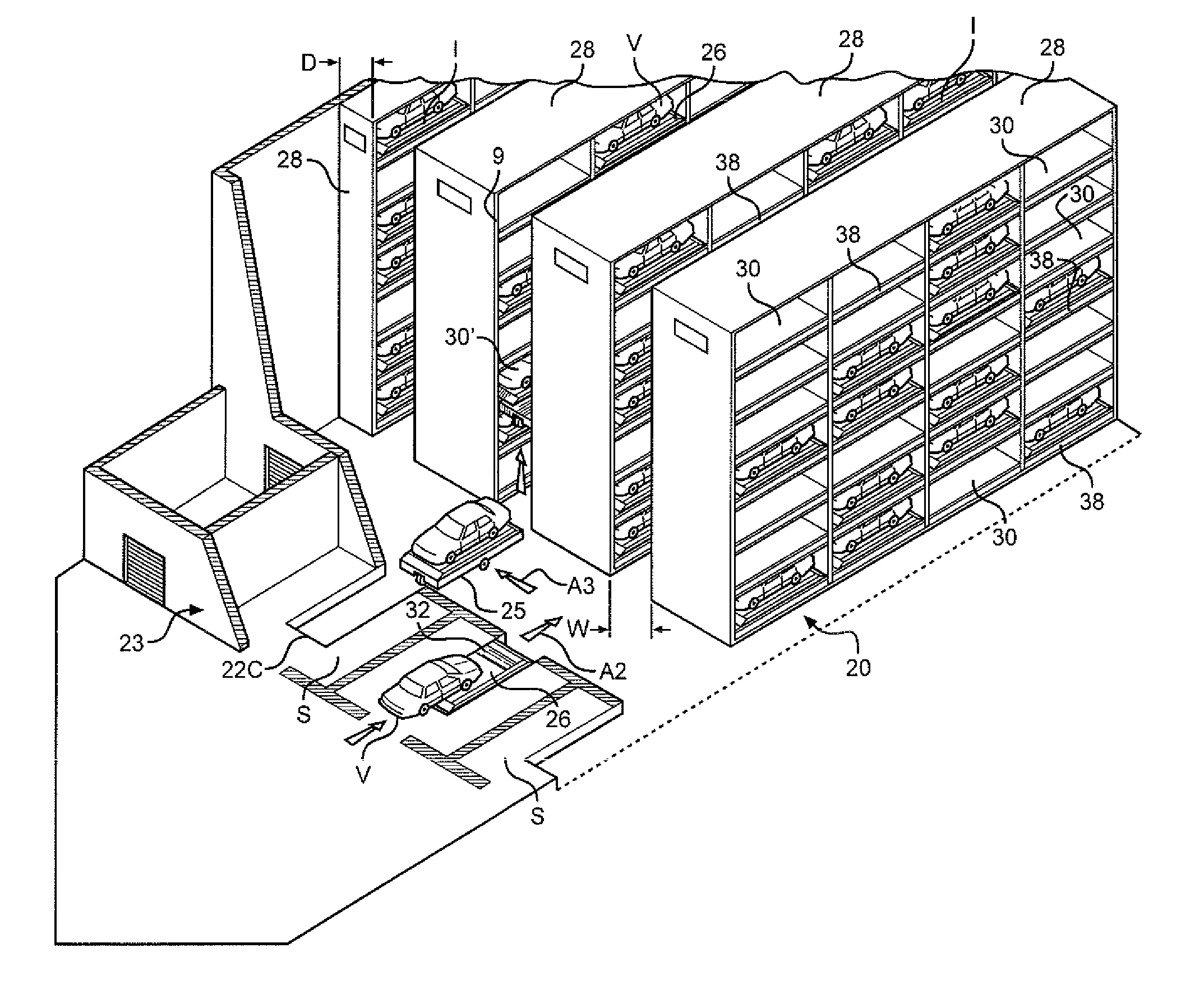
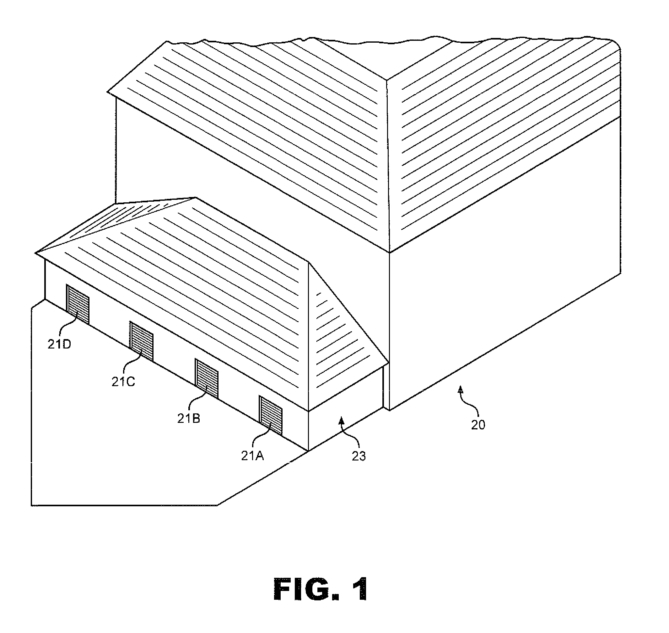
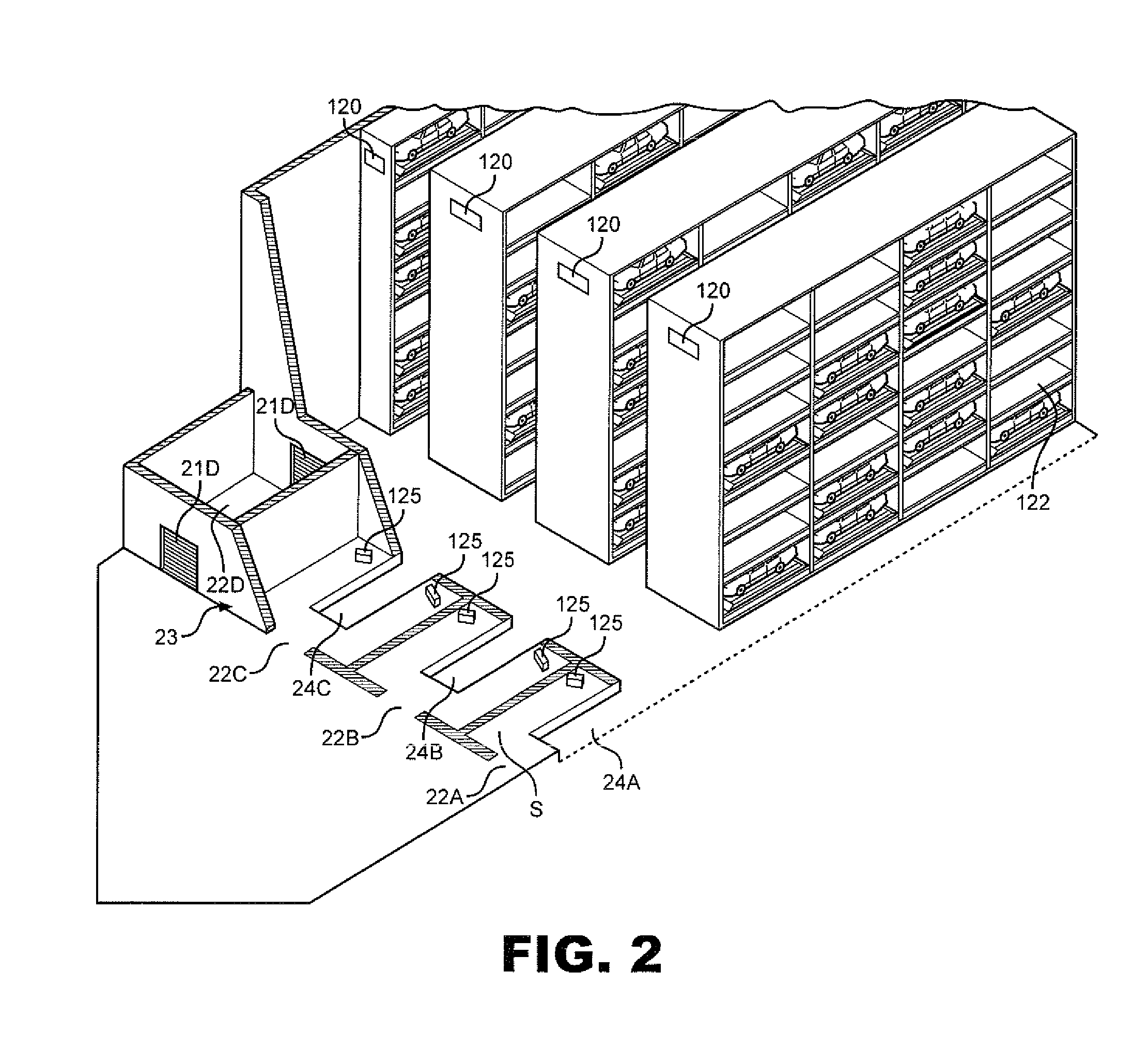
[0057]With specific reference to FIGS. 13 and 14, the invention is shown wherein the parking cubicles are configured to receive vehicles lengthwise. In this embodiment a fully automated parking garage system 20′ is disclosed that includes a plurality of entrance and / or exit doors, with only exit door 21D′ being shown, into spaced loading and off-loading bays 22A′-22D′ within a first portion 23′ of the system 20′. Within each bay is a recessed docking surface shown at 24A′, 24R′ and 24C′. The depth of each recessed docking surface is sufficient to allow the AGVs 25, that have been previously described herein, carrying a vehicle support trays 26 to be parked within the docking or loading area such that a conventional automotive vehicle “V” may be directly driven onto the support tray when entering the bay areas of the garage, see FIG. 13, or from the support tray to a travel surface “S” when a vehicle is exiting the garage system, see FIG. 14.

[0058]The parking garage includes a plural...

first embodiment

[0064]The drive motors and the vertical drive gears and horizontal drive wheels are the same as described with respect to the first embodiment with the exception of the gears 90 for engaging the track teeth or chain rollers associated chains mounted on opposite side of each of the parking cubicles are mounted at the opposite ends of the AGV and toward the opposite sides thereof.

[0065]With reference to FIGS. 15 and 16, a variant of the second embodiment is shown wherein the vehicles “V” are transported directly on an upper surface of the AGVs. This is possible because the vehicles will be aligned to be driven or rolled directly from the AGVs into or from the parking cubicles 30′. By placing a vehicle in neutral, it may be easily moved into a parking cubicle or pulled there from because the vehicle wheels are aligned to permit such movement. In FIG. 15, a vehicle “V” is shown being pushed into a parking cubicle whereas FIG. 16 shows the vehicle being pulled from the cubicle.

[0066]Furt...


PUM


Abstract

A system and method for optimizing the parking and storage capacity of a vehicle parking garage wherein rows of vertical columns of parking spaces or cubicles are spaced in opposing relationship with one another such that at least one automatic guided and self propelled vehicle (AGV), with or without a vehicle support tray mounted thereon, is vertically movable in engagement with the opposing racks or chains that extend on opposite sides of the vertical columns of parking cubicles so that a vehicle may be loaded onto the AGV and thereafter transferred to, and later removed from a parking cubicles and transferred to an exit of the garage. If tray are used on the AGV, additional trays are stored in storage spaces adjacent each parking cubicle.

Description

BACKGROUND OF THE INVENTION[0001]1. Field of the Invention[0002]This application is directed to the general field of parking garages for automotive vehicles and more particularly to automated vehicle parking garages and / or storage systems wherein vertical stacks or columns of vehicle storage cubicles are laid out in generally parallel rows that are generally equally spaced by isles that are of generally equal width and of a size to permit one or more automatically guided vehicles (AGVs) to move both horizontally and vertically between the rows of storage cubicles.[0003]2. Brief Description of the Related Art[0004]Adequate automotive vehicle parking spaces and short and long term storage spaces for such vehicles is an ever growing problem in most major cities in the world. Further, the parking problems are not limited to cities, but often to public transit areas such as airports, docking terminals, railway stations and the like as well as to commercial and entertainment facilities su...

Claims


Application Information

Patent Timeline
IPC IPC(8): E04H6/18E04H6/22E04H6/12
CPCE04H6/225
Inventor BENEDICT, CHARLES E.PFEIFER, BRIAN G.YATES, CHRISTIAN A.BLADEN, SCOTT K.LACKINGER, RICHARD E.DOBBS, JAMES R.
Owner GEBRR BECKER
Why Eureka
Try Eureka