Control, Collection and Use of Metal-Air Battery Pack Effluent

Active Publication Date: 2012-02-16
TESLA INC
View PDF0 Cites 69 Cited by
  • Summary
  • Abstract
  • Description
  • Claims
  • Application Information

AI Technical Summary

Benefits of technology

[0008]The present invention provides a system and method for maintaining an ambient oxygen concentration below a preset concentration while chargi

Problems solved by technology

While metal-air cells offer a number of advantages over a conventional rechargeable battery,

Method used


Image

  • Control, Collection and Use of Metal-Air Battery Pack Effluent
  • Control, Collection and Use of Metal-Air Battery Pack Effluent
  • Control, Collection and Use of Metal-Air Battery Pack Effluent

Examples


Embodiment Construction

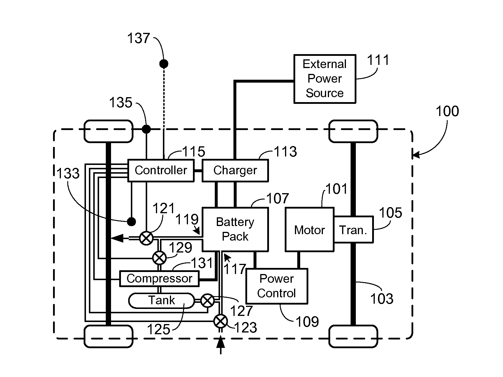
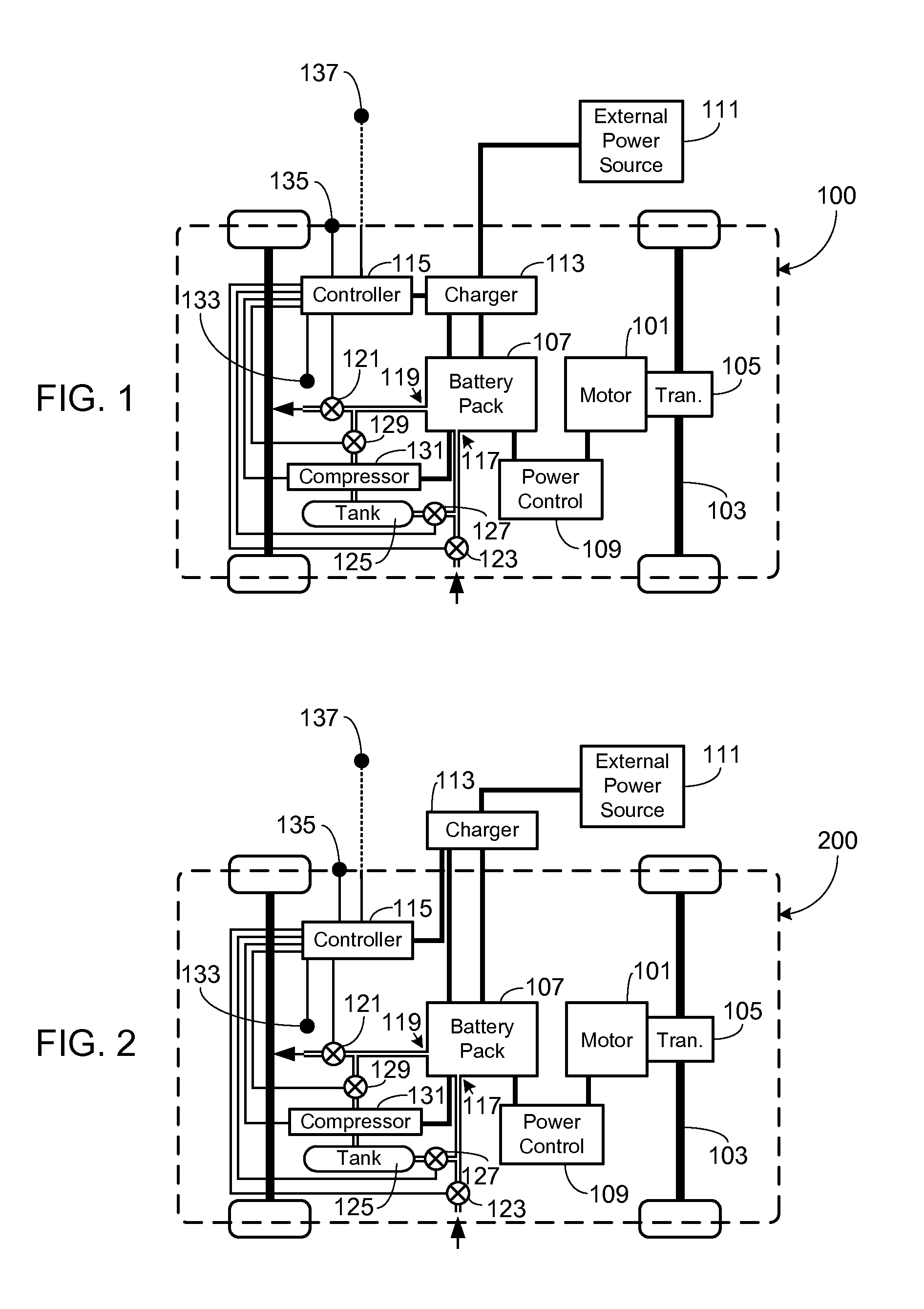
[0029]In the following text, the terms “battery”, “cell”, and “battery cell” may be used interchangeably. The term “battery pack” as used herein refers to one or more individual batteries that are electrically interconnected to achieve the desired voltage and capacity for a particular application, the individual batteries typically contained within a single piece or multi-piece housing. The term “electric vehicle” as used herein refers to an all-electric vehicle, also referred to as an EV, a plug-in hybrid vehicle, also referred to as a PHEV, or a hybrid vehicle (HEV), and / or a hybrid vehicle utilizing multiple propulsion sources one of which is an electric drive system. It should be understood that identical element symbols used on multiple figures refer to the same component, or components of equal functionality. Additionally, the accompanying figures are only meant to illustrate, not limit, the scope of the invention and should not be considered to be to scale.

[0030]Given the hig...


PUM


Abstract

A system and method for maintaining an ambient oxygen concentration below a preset concentration while charging a metal-air battery pack is provided, the system utilizing an on-board means for collecting and storing the oxygen-rich effluent generated during the charge cycle.

Description

CROSS-REFERENCE TO RELATED APPLICATION[0001]This application is a continuation-in-part of U.S. patent application Ser. Nos. 12 / 887,557, filed Sep. 22, 2010, and 13 / 013,852, filed Jan. 26, 2011, and claims benefit of the filing date of U.S. Provisional Patent Application Ser. No. 61 / 372,351, filed Aug. 10, 2010, the disclosures of which are incorporated herein by reference for any and all purposes.FIELD OF THE INVENTION[0002]The present invention relates generally to batteries and, more particularly, to means for minimizing the flammability risks associated with metal-air cells while increasing metal-air battery pack efficiency through utilization of battery pack effluent.BACKGROUND OF THE INVENTION[0003]A metal-air cell is a type of battery that utilizes the same energy storage principles as a more conventional cell such as a lithium ion, nickel metal hydride, nickel cadmium, or other cell type. Unlike such conventional cells, however, a metal-air cell utilizes oxygen as one of the ...

Claims


Application Information

Patent Timeline
IPC IPC(8): G06F7/00B60L11/18
CPCH01M8/04089H01M8/0606Y02E60/50H01M12/08H01M2220/20H01M10/445Y02E60/10
Inventor HERMANN, WESTON ARTHURSTRAUBEL, JEFFREY BRIAN
Owner TESLA INC
Why Eureka
Try Eureka