
Brake pedal depressing device and method of using the same

Inactive Publication Date: 2012-03-01
TWN ENTERPRISES
View PDF12 Cites 2 Cited by
  • Summary
  • Abstract
  • Description
  • Claims
  • Application Information

AI Technical Summary

Benefits of technology

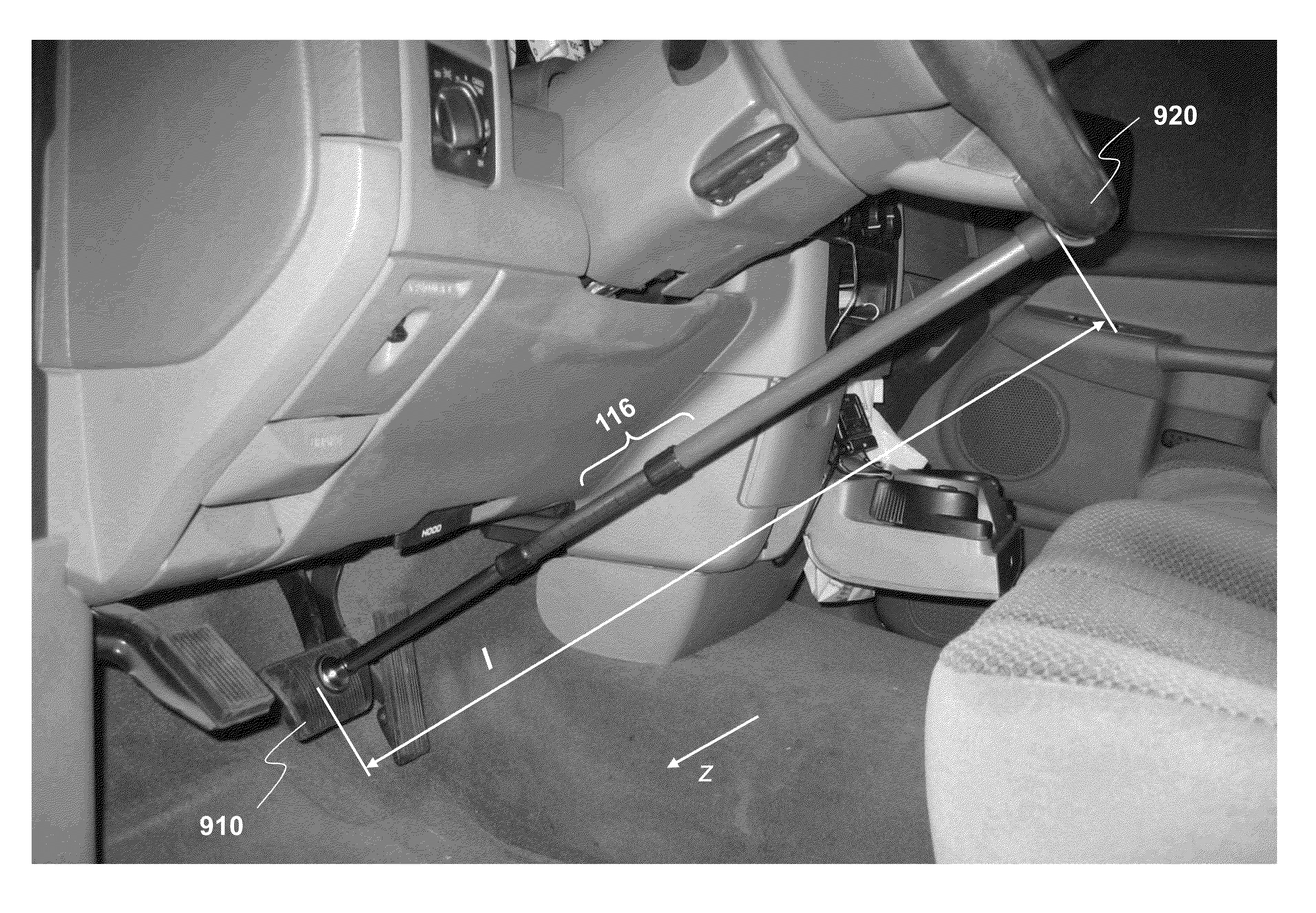
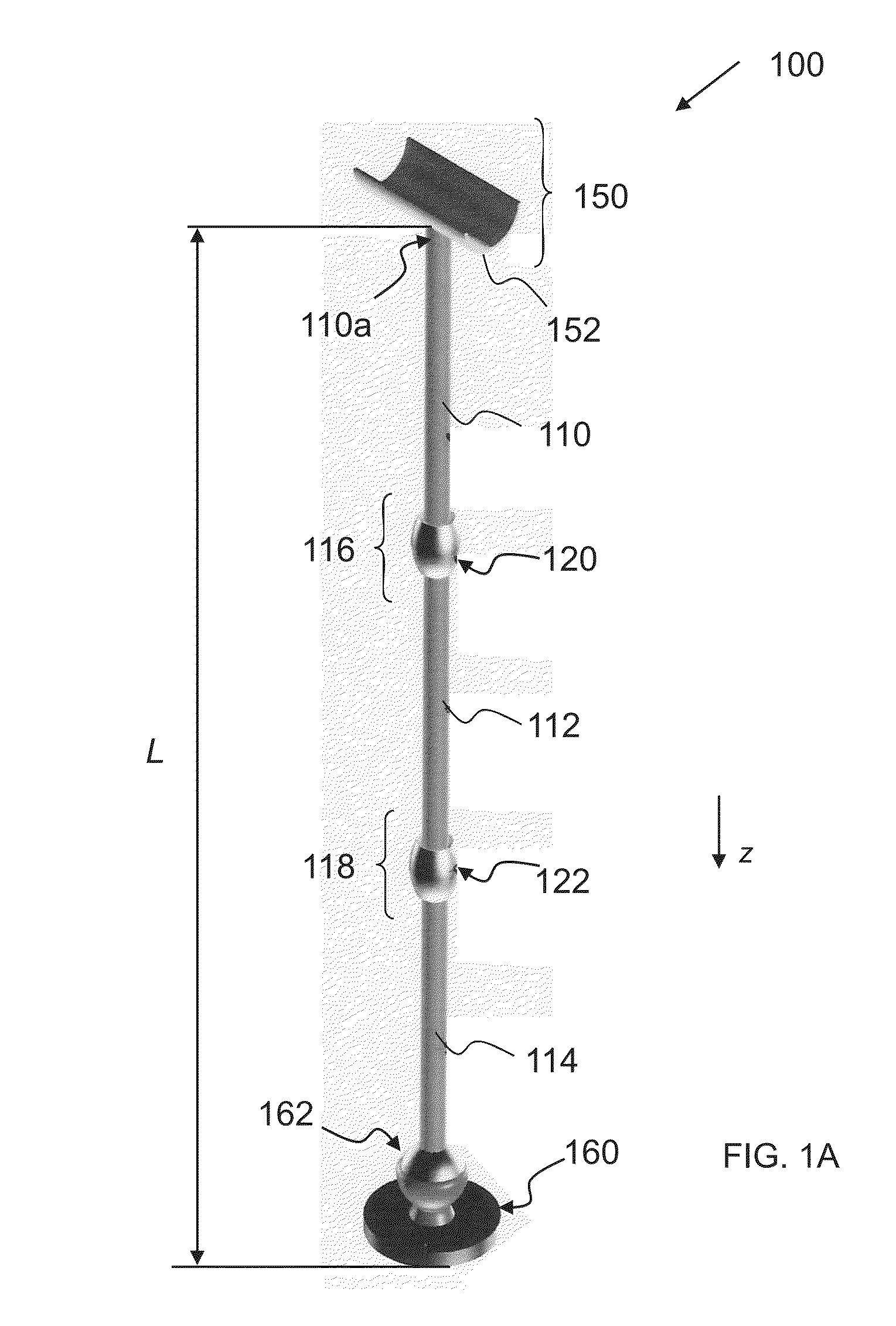
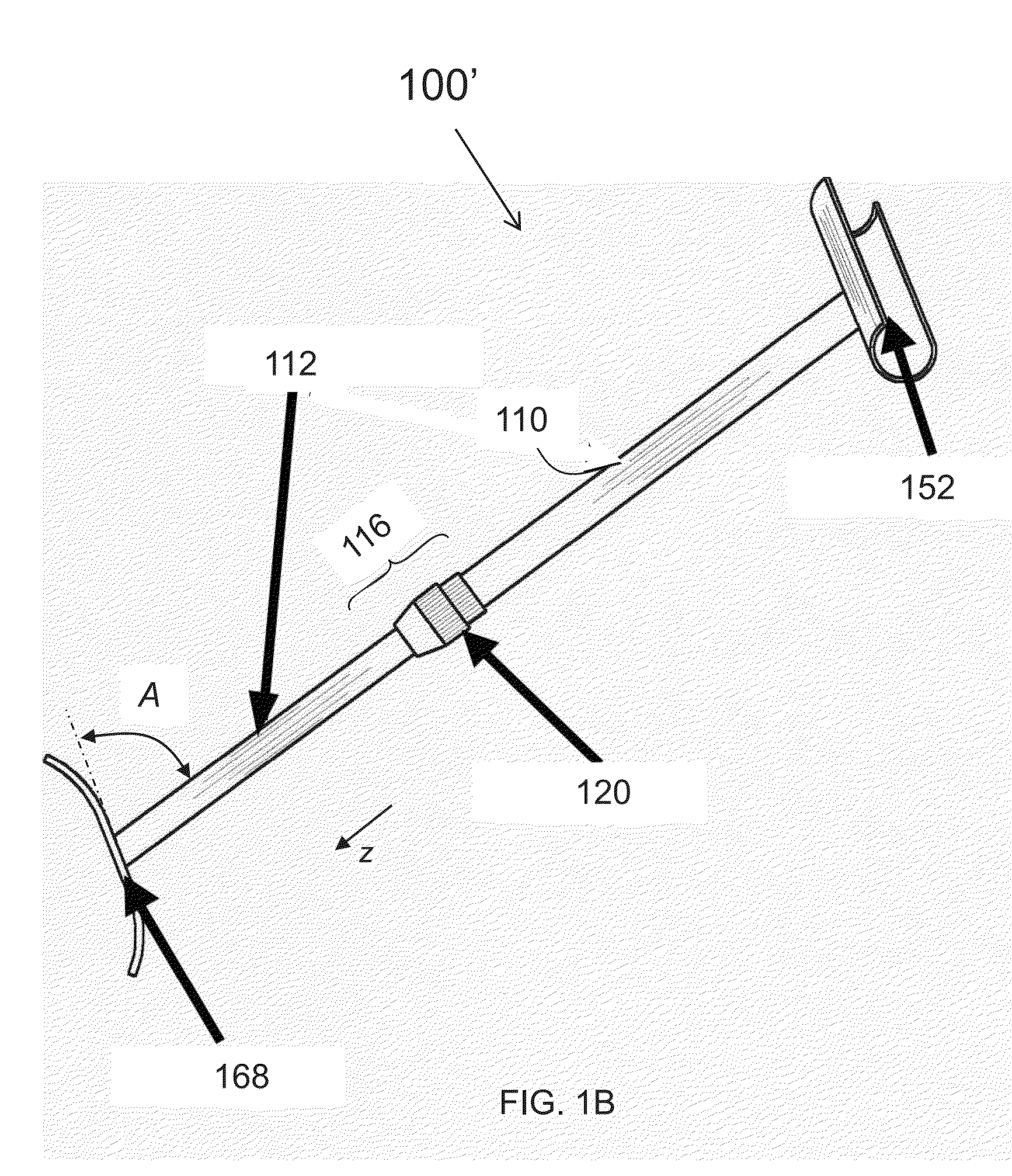
[0009]Embodiments of a method of the invention include adjusting a length of an elongated unit that includes a plurality of sections having linear extent, an angularly turnable foot attached to one of the section, and a cradle transversely attached to one of the sections from the plurality of sections. An embodiment can further include inserting the elongated unit between the steering wheel and the brake pedal such that the transverse cradle receives a portion of the steering wheel while the foot depresses the brake pedal. Additionally, the method may include causing a feedback system of the unit to generate an output, whether an optical output or an audible output perceived by the user, in response to the cradle having received a portion of the steering wheel. Insertion of the unit may include twisting of the unit around an axis of the unit thereby unlocking at least one lock disposed within an at least one section of the unit. The unlocking of a lock facilitates the adjustment of the length of the unit by permitting the sections to slide with respect one another. In a specific embodiment, the sliding and length adjustment may occur telescopically and cause the unit to reach an extant exceeding a shortest distance between depressed brake pedal and the steering wheel.

Problems solved by technology

In practice, however, there is often only a single driver going on a road-trip.
A single person finds it rather difficult to check the performance of the brakes.
In practice, such “on-the-spot” solution is neither optimal nor versatile because, on one hand, an irregular article cannot be reliably fastened to and depress the brake pedal for a time period necessary to conclude the inspection and, on the other hand, the same irregular article cannot be used in every vehicle due to difference in dimensions of vehicular cabins and / or different resistance of different brake pedals.
In particular, solutions offering depressing a brake pedal by “wedging” an elongated element such as a stick, tube, or rod between either the driver's seat and the brake pedal or a dash board and the brake pedal do not take into account the design of the vehicular cabin.
Indeed, it is well known the fact that there exists no uniformity in design of either the vehicular seats or dash boards, which makes it problematic to accommodate different distances between the seat / board and brake pedal.
Moreover, some vehicles are lacking a dash-board surface that could provide for similar accommodation.
As far as using a driver seat is concerned, not only is it soft but, in practice, many driver seats are worn out or torn apart and simply do not provide a solid reference surface for entrapping or fixing one of the ends of a wedging element.
More often than desired, however, such protruding beyond the extend of the vehicle mirror is out of working order, for example broken off.

Method used


Image

  • Brake pedal depressing device and method of using the same
  • Brake pedal depressing device and method of using the same
  • Brake pedal depressing device and method of using the same

Examples


Embodiment Construction

[0021]References throughout this specification to “one embodiment,”“an embodiment,”“a related embodiment,” or similar language mean that a particular feature, structure, or characteristic described in connection with the referred to “embodiment” is included in at least one embodiment of the present invention. Thus, appearances of the phrases “in one embodiment,”“in an embodiment,” and similar language throughout this specification may, but do not necessarily, all refer to the same embodiment. It is to be understood that no portion of disclosure, taken on its own and / or in reference to a figure, is intended to provide a complete description of all features of the invention.

[0022]In addition, in drawings, with reference to which the following disclosure may describe features of the invention, like numbers represent the same or similar elements wherever possible. In the drawings, the depicted structural elements are generally not to scale, and certain components are enlarged relative t...


PUM

PropertyMeasurementUnit
Lengthaaaaaaaaaa
Forceaaaaaaaaaa
Distanceaaaaaaaaaa

Abstract

A system and method for restraining a vehicular brake pedal in depressed position. A system includes an elongated multi-section unit the length of which can be adjusted within a dynamic range by changing mutual positioning of the sections and locking the unit with an internal lock once the desired length has been achieved. Fastening of the internal lock is achieved through twisting of the unit around its axis. The restraining of the brake pedal is carried out with respect to a steering wheel, a portion of which is received and accommodated by a cradle on one end of the unit while a turnable foot on the other end of the system depresses the pedal.

Description

CROSS-REFERENCE TO RELATED APPLICATIONS[0001]This patent application claims benefit and priority from U.S. Provisional Patent Application No. 61 / 377,961 filed on Aug. 29, 2010 and titled “Brake Pedal Depressing Device and Method of Using the Same.” The disclosure of the above-mention patent application is incorporated herein by reference in its entirety.TECHNICAL FIELD[0002]The present invention relates to the field of automotive inspections and, more particularly, to inspection of vehicular brakes.BACKGROUND ART[0003]Federal Motor Carrier Safety Administration and Department of Transportation requires periodic inspection of the vehicular brakes on all commercial vehicles (in particular, both pre- and post-transportation trip). Conventional practice of confirming that a vehicular brake system is operational is for one person to depress the brake pedal in the cabin of the vehicle while another person, standing behind the vehicle, verifies that the brake lights are operational and tha...

Claims


Application Information

Patent Timeline
IPC IPC(8): B66F19/00B23P11/00B66F15/00
CPCB60T17/221B60T7/042Y10T29/49826Y10T70/5965Y10T70/5894Y10T70/573
Inventor NEIBURGER, THOMAS W.NIEMEYER, BRET LEE
Owner TWN ENTERPRISES
Features
  • Generate Ideas
  • Intellectual Property
  • Life Sciences
  • Materials
  • Tech Scout
  • Unparalleled Data Quality
  • Higher Quality Content
  • 60% Fewer Hallucinations
Learn More