Detachable table device

Active Publication Date: 2012-03-01
HABITEX
View PDF12 Cites 1 Cited by
  • Summary
  • Abstract
  • Description
  • Claims
  • Application Information

AI Technical Summary

Benefits of technology

[0005]Therefore, the object of the present invention is to provide a detachable table device that occupies a relatively small amount of

Problems solved by technology

Therefore, it is inconve

Method used


Image

  • Detachable table device
  • Detachable table device
  • Detachable table device

Examples


Example

[0019]Before the present invention is described in greater detail, it should be noted that like elements are denoted by the same reference numerals throughout the disclosure.

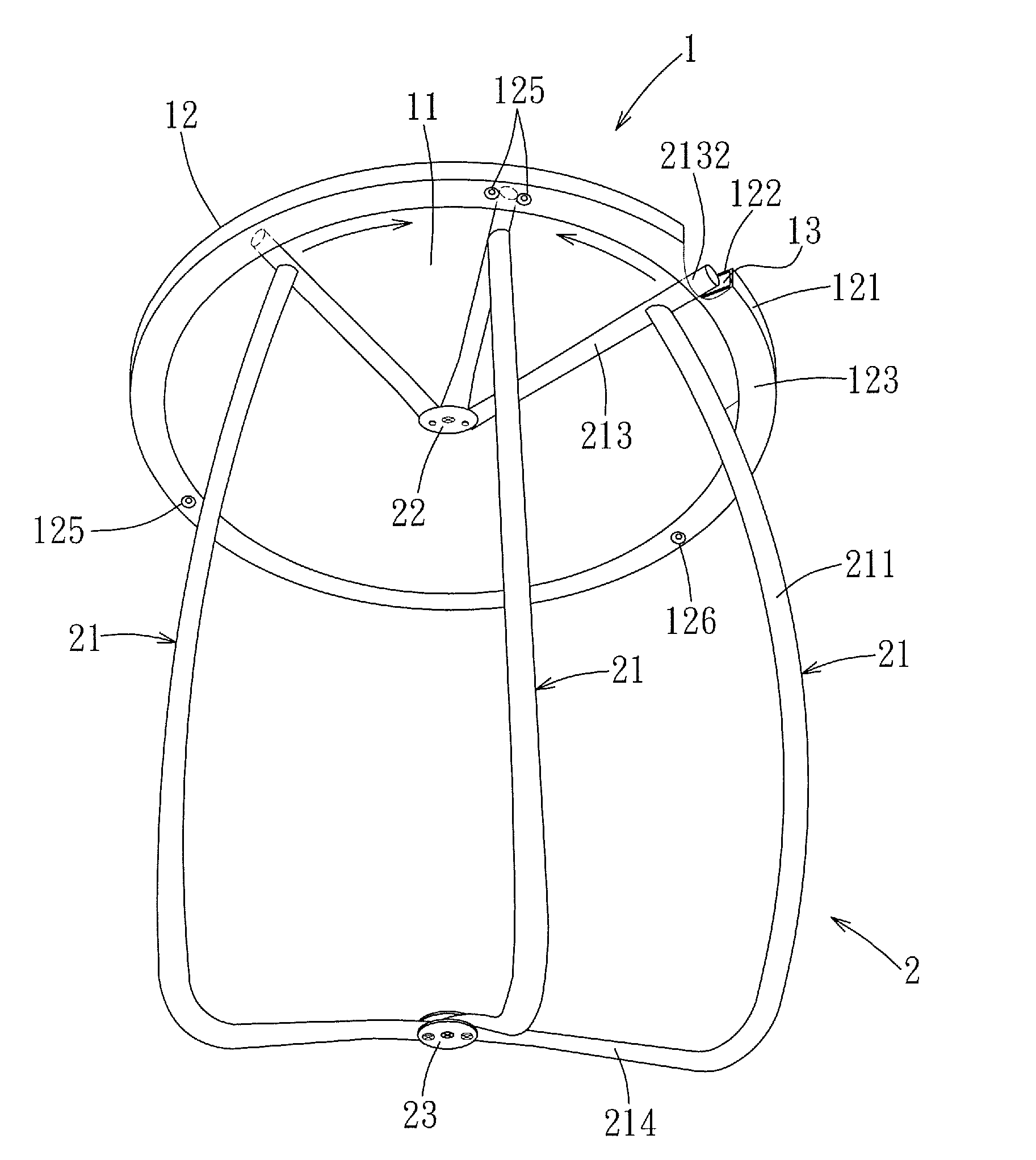
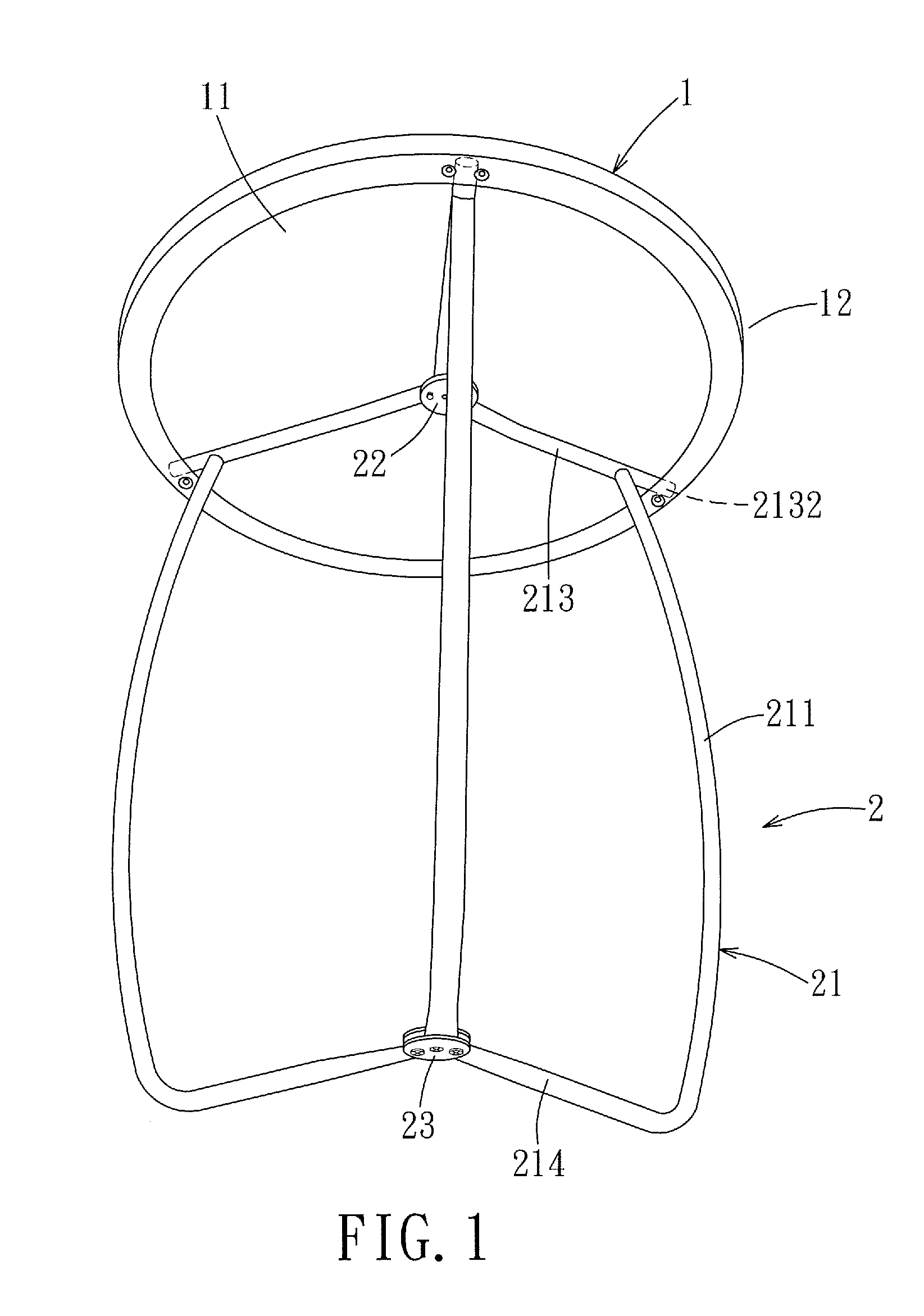
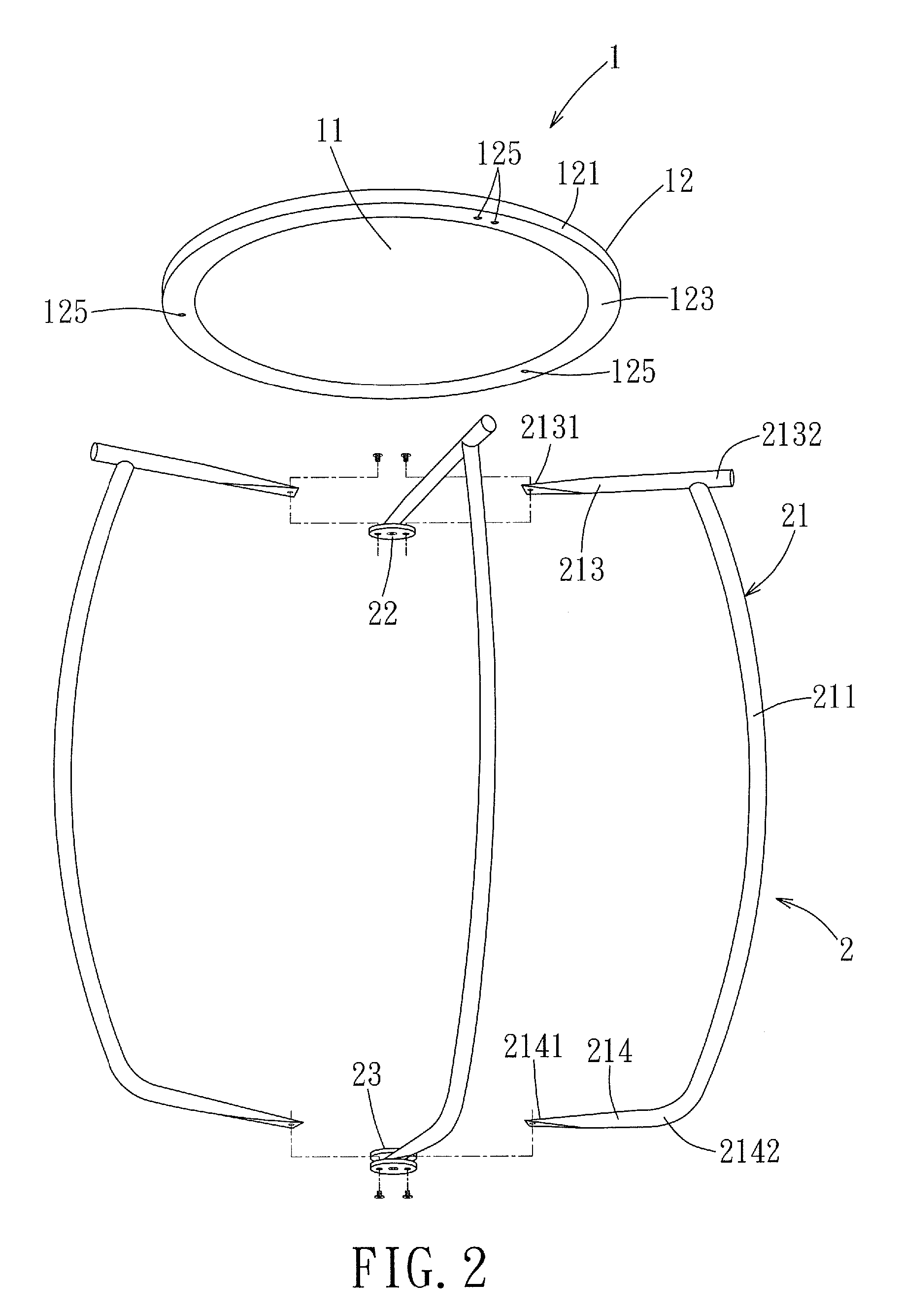
[0020]Referring to FIGS. 1, 2 and 5, the first preferred embodiment of a detachable table device according to the present invention is shown to include a table top 1, and a foldable leg device 2.

[0021]Referring further to FIG. 3, the table top 1 has a circular top plate portion 11, and a circumferential portion 12 connected integrally to the top plate portion 11. The circumferential portion 12 has an inner annular surface 120 formed with a radially and outwardly extending annular engaging groove 13. The annular engaging groove 13 is defined among an annular top wall 122, an annular bottom wall 123, and an annular side wall 121 interconnecting the annular top and bottom walls 122, 123. In this embodiment, the circumferential portion 12 is formed with a plurality of bumps 124 (only two are shown in FIG. 3) that ar...


PUM


Abstract

A detachable table device includes a foldable leg device detachably connected to a table top and operable to support the table top when in an extended state and to separate from the table top when in a folded state. A circumferential portion of the table top has an inner annular surface formed with a radially and outwardly extending annular engaging groove. The leg device includes a pivot unit for interconnecting at least three leg members such that the leg members are pivotable relative to the pivot unit to be angularly equidistant when the leg device is in the extended state, and to be moved toward each other when the leg device is in the folded state. Each leg member includes an engaging end portion disposed movably in and engaging releasably the engaging groove in the circumferential portion of the table top.

Description

BACKGROUND OF THE INVENTION[0001]1. Field of the Invention[0002]The invention relates to a table device, and more particularly, to a detachable table device.[0003]2. Description of the Related Art[0004]Generally, a conventional table device with unfolded legs occupies a relatively large area when not in use. Therefore, it is inconvenient to store and carry. In addition, tools are required to assemble or disassemble such a table device.SUMMARY OF THE INVENTION[0005]Therefore, the object of the present invention is to provide a detachable table device that occupies a relatively small amount of space when not in use, and that has a foldable leg device which can be manually attached to or detached from a table top without tools.[0006]According to the present invention, a detachable table device comprises:[0007]a table top having a circumferential portion, the circumferential portion having an inner annular surface formed with a radially and outwardly extending annular engaging groove; a...

Claims


Application Information

Patent Timeline
IPC IPC(8): A47B3/12A47B3/06
CPCA47B3/12A47B3/002
Inventor HSIEH, DUAN-CHENG
Owner HABITEX
Why Eureka
Try Eureka