System and method for operating an internal combustion engine

a technology of internal combustion engine and system, which is applied in the direction of combustion engine, valve arrangement, machine/engine, etc., can solve the problems of affecting engine performance, efficiency, exhaust pollutants, other engine characteristics, and diesel engines operating in such environmental conditions are subject to greater loads, and the effect of reducing the number of cylinders

Inactive Publication Date: 2012-03-01
GENERAL ELECTRIC CO
View PDF13 Cites 9 Cited by
  • Summary
  • Abstract
  • Description
  • Claims
  • Application Information

AI Technical Summary

Problems solved by technology

These environmental conditions can adversely affect engine performance, efficiency, exhaust pollutants, and other engine characteristics.
For example, diesel engines operating in such environmental conditions are subject to greater loads, lower atmospheric pressures, lower temperatures due to colder climate, lower air density due to lower atmospheric pressure, and so forth.
At such conditions, the compressor and the turbocharger speed can increase beyond a preselected limit without suitable control measures.
Surge is one unstable operating condition of the compressor.
Events, both external and internal to the compressor, may occasionally move compressor operation to a point that is beyond its stability limit, causing a surge condition.
Because of the lower initial pressure, the pressure at the end of the compression stroke is reduced, resulting in a lower effective compression ratio.
The lower amount of charge in the cylinder due to the Miller cycle would result in a loss in power.
Redesign of the compressor increases the cost and complexity of implementing the Miller cycle.
However, exhausting compressed air directly to the turbine results in wastage of energy.
Also, such a strategy is not feasible in systems where an exhaust pressure is greater than an intake pressure.

Method used


Image

  • System and method for operating an internal combustion engine
  • System and method for operating an internal combustion engine
  • System and method for operating an internal combustion engine

Examples


Embodiment Construction

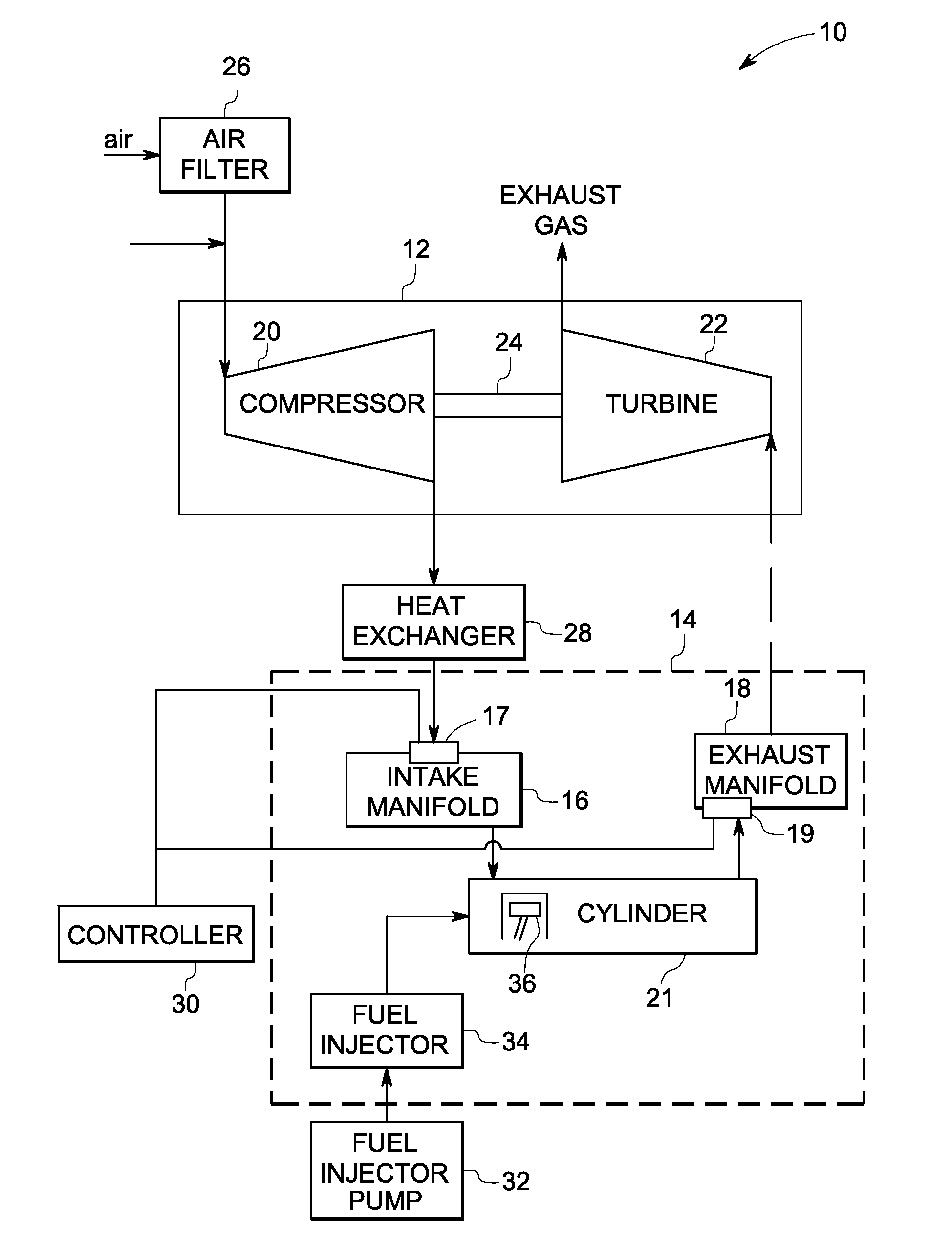
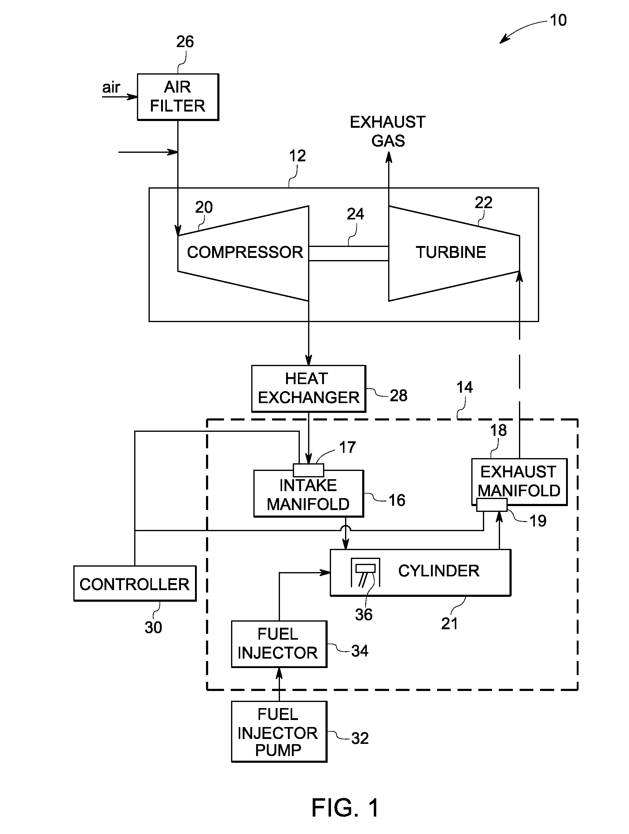
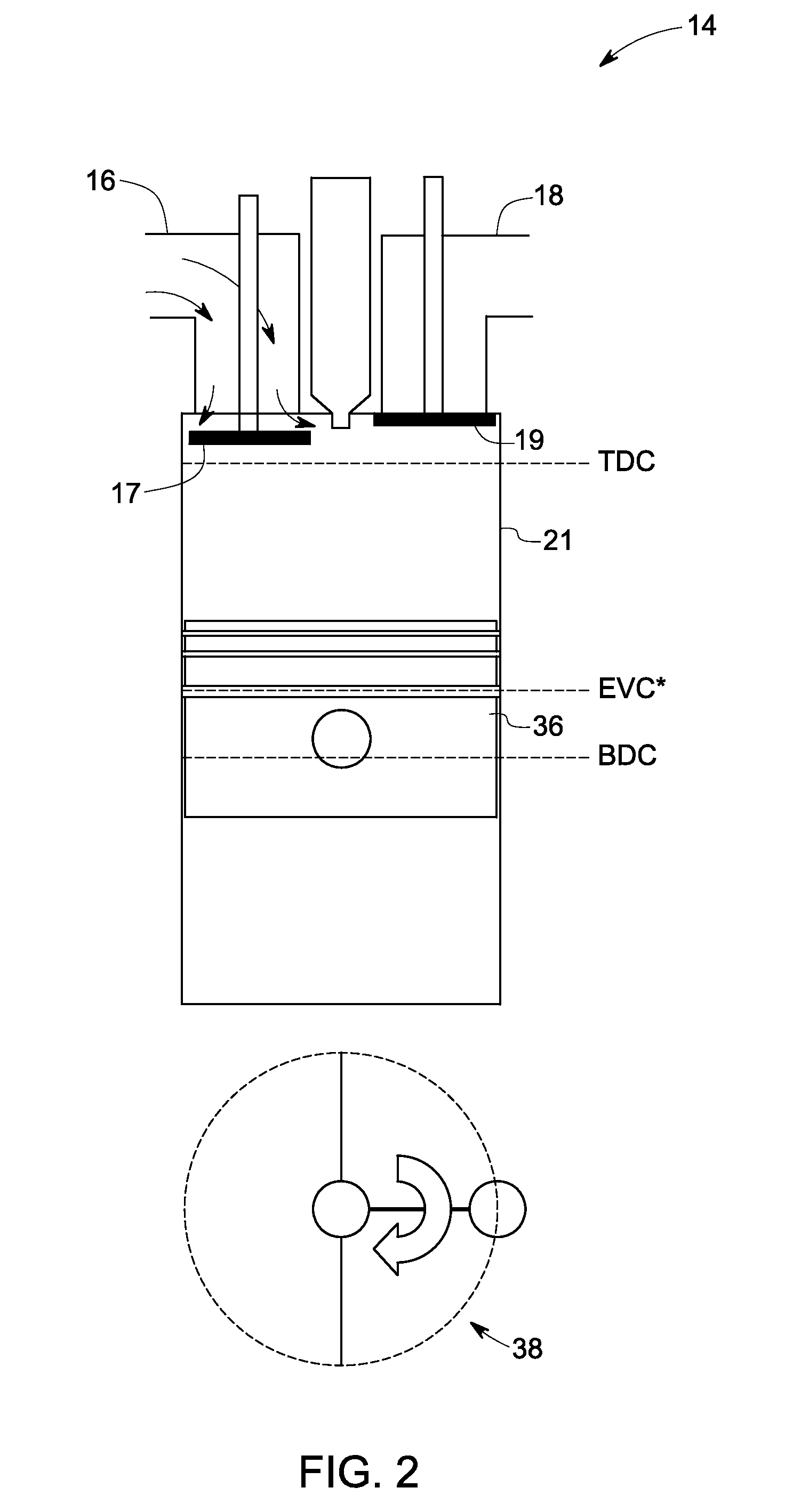
[0015]In accordance with certain embodiments of the present invention, a method of operating an internal combustion engine in accordance with a Miller cycle is disclosed. The method includes moving a piston from a top dead center position towards a bottom dead center position in an engine cylinder and closing an intake valve of the internal combustion engine when a piston is about the bottom dead center position in the engine cylinder. The method includes opening an exhaust valve for a predetermined time period when the piston is about the bottom dead center position of the engine cylinder after closing the intake valve during a compression stroke of the piston so as to exhaust a predetermined quantity of fresh charge from the engine cylinder via the exhaust valve. In accordance with a specific embodiment of the present invention an internal combustion engine operated in accordance with a Miller cycle is disclosed. As discussed herein below, the exhaust valve of the engine is re-ope...


PUM


Abstract

An internal combustion engine is operated in accordance with a Miller cycle. The engine includes a piston disposed in the engine cylinder and configured to reciprocate between a top dead center position and a bottom dead center position of the engine cylinder. An air intake valve is coupled to the cylinder. The air intake valve is closed when the piston is about the bottom dead center position in the engine cylinder. An exhaust valve is coupled to the engine cylinder. The exhaust valve is opened for a predetermined time period when the piston is about the bottom dead center position of the engine cylinder after closing the intake valve so as to exhaust a predetermined quantity of fresh charge from the engine cylinder via the exhaust valve.

Description

BACKGROUND[0001]The invention relates generally to a system and method for operating an internal combustion engine and, more specifically, to a system and method for operating an internal combustion engine in accordance with a Miller cycle for a turbocharged system.[0002]In certain applications, the turbocharged engines are used in different environmental conditions. These environmental conditions can adversely affect engine performance, efficiency, exhaust pollutants, and other engine characteristics. For example, diesel engines operating in such environmental conditions are subject to greater loads, lower atmospheric pressures, lower temperatures due to colder climate, lower air density due to lower atmospheric pressure, and so forth. At such conditions, the compressor and the turbocharger speed can increase beyond a preselected limit without suitable control measures.[0003]Surge is one unstable operating condition of the compressor. Most compressors have a stability limit that is...

Claims


Application Information

Patent Timeline
Patent Type & Authority Applications(United States)
IPC IPC(8): F01L1/00
CPCF02D13/0269F02D13/0273Y02T10/142F02D23/02F02D13/028Y02T10/12
Inventor KLINGBEIL, ADAM EDGARHWANG, WONTAEPRIMUS, ROY JAMES
Owner GENERAL ELECTRIC CO
Why Eureka
Try Eureka