Method and apparatus for applying vibrations during borehole operations

a technology of vibration and operation, applied in the direction of drilling machine and method, borehole/well accessories, drilling accessories, etc., can solve the problems of increased axial friction, no longer helping gravity, and difficult access, so as to ease any torsion forces

Inactive Publication Date: 2012-03-01
MISC
View PDF4 Cites 77 Cited by
  • Summary
  • Abstract
  • Description
  • Claims
  • Application Information

AI Technical Summary

Benefits of technology

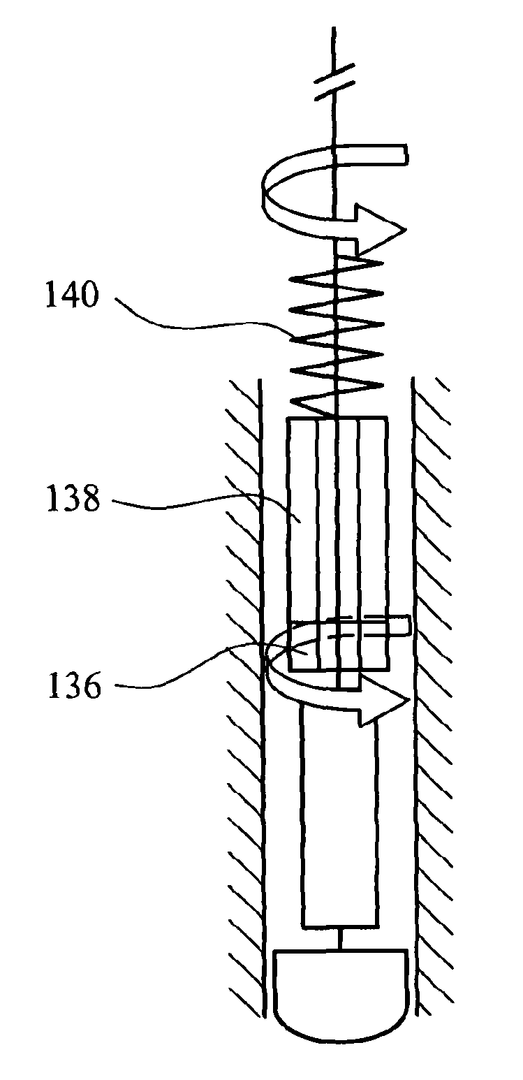
[0020]Prior to orienting the bent sub, torsion vibrations can be applied at the predetermined frequency to the system to ease any torsion forces in the system.
[0022]The steps of applying vibrations at the predetermined frequency to the system to ease any torsion forces in the system, orienting the bent sub by applying weight on bit to deviate the tool face direction due to the torque reaction when drilling and controlling the swing amplitude of the torsional vibration so as to control the amount of deviation in drilling trajectory in the tool face direction arising from the bent sub can be periodically repeated.

Problems solved by technology

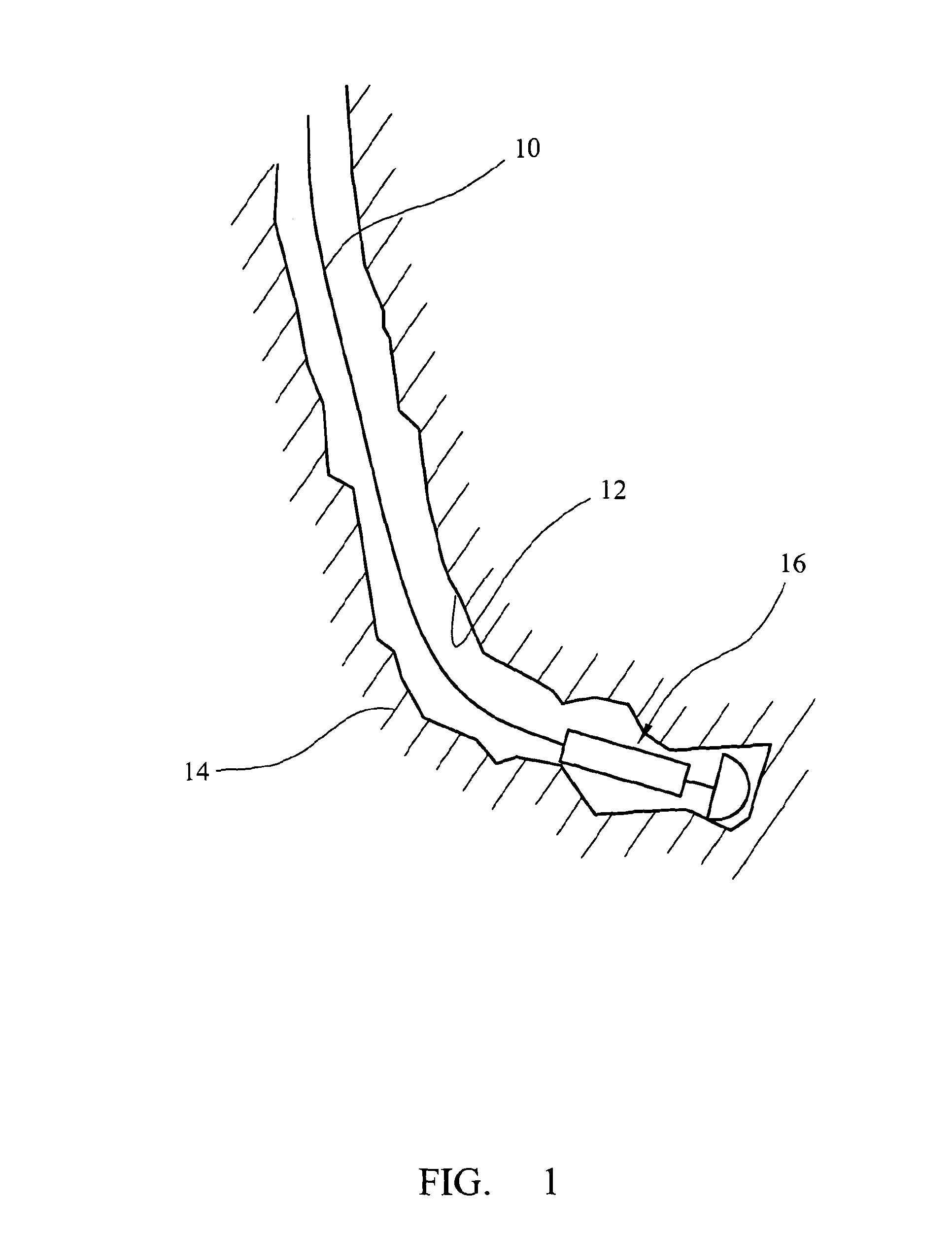
However, where the borehole deviates from vertical, particularly where it becomes close to horizontal, gravity no longer assists and it can become necessary to push a tool into the borehole if it is to reach the bottom and, apply weight on bit in the case of drilling.
Consequently, drill pipe has been used for both drilling and other well interventions where access can be difficult.
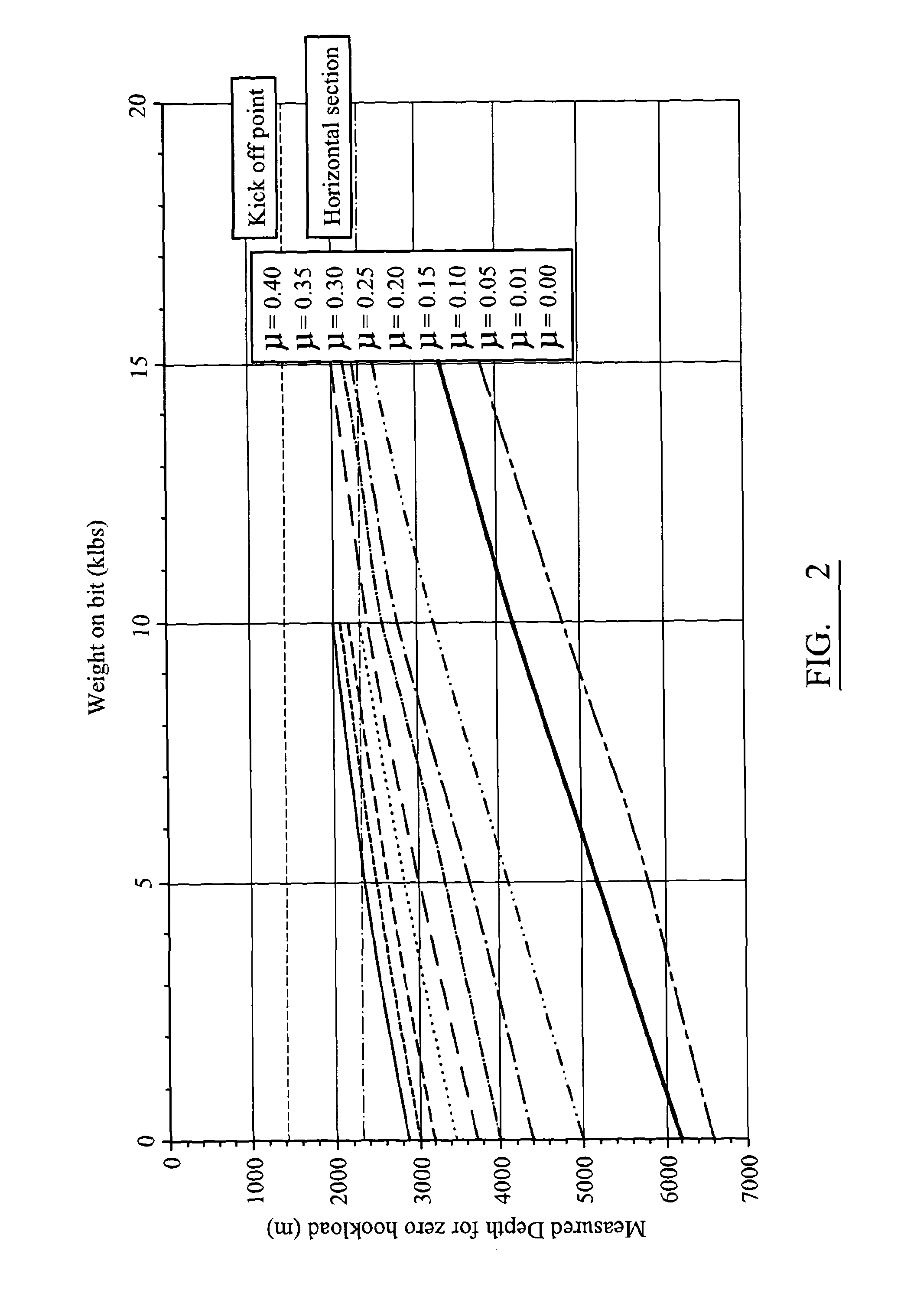
There are a number of problems associated with sliding drilling using a bent sub, in particular, sliding drilling encounters greater axial friction (drag) with the borehole wall, leading to reduced effectiveness of weight transfer to the bit, and a greater propensity for differential sticking of the drill sting components in regions of permeable formation in the well.
These, and other problems, have lead to the development of downhole adjustable rotary steerable systems, which allow deviation of the well trajectory while rotating the drill string.
While such tubing has a degree of rigidity, its desirable flexibility can lead to certain problems.
If a long length of CT is fed into a well and encounters some resistance, for example due to axial friction from contact with the borehole wall, pushing from the surface can lead to buckling of the CT.
This buckling can increase the contact of the tubing with the borehole wall, impeding effective weight transfer to the bottom of the CT.
Friction between the CT and the borehole wall can initiate this problem, since the CT must slide over the borehole wall when it is introduced into the well.
However, the problem discussed above limits its use at great depths or with high deviation from vertical.
The limitations on the operating envelope of CT mean that it can be difficult to obtain full benefit of the reduction in cost and environmental impact in many wells.
To date, none of these have been particularly effective.

Method used


Image

  • Method and apparatus for applying vibrations during borehole operations
  • Method and apparatus for applying vibrations during borehole operations
  • Method and apparatus for applying vibrations during borehole operations

Examples


Embodiment Construction

[0040]The invention will be described in relation to a coiled tubing drilling operation. However, it will be apparent that it can apply to other forms of drilling or well operations. For example, the benefit of the invention can be obtained in drilling with conventional drill pipe, especially when it is operating in sliding mode such as in directional drilling applications. Also, a similar benefit can be obtained with other operations where it is necessary to advance a downhole tool into the well using CT or drill pipe. Other applications involve running in casing, production or completion tubing, expandable tubulars, fishing operations, and wireline logging and drilling operations.

[0041]In order to avoid the problems of axial friction (drag) associated with the prior art systems discussed above, torsional vibrations are applied to the drill string (or tool string) in order to move the friction from the static domain to dynamic domain, and to change the friction vector from axial to...


PUM


Abstract

A method of conducting borehole operations using a system including an elongate tubular conveyance that is moved through the borehole, the method comprising imposing a torsional vibration at a predetermined frequency on the tubular conveyance as it is moved through the borehole:wherein the predetermined frequency is obtained by determining the frequency-dependent mobility of the system based on the relationship between rotational velocity and torque for the system; and imposing torsional vibrations at a frequency where the relationship is optimised.

Description

TECHNICAL FIELD[0001]This invention relates to methods and apparatus for applying vibrations to downhole tools in borehole operations. In particular, the invention relates to such methods and apparatus that are applicable to operations such as those conducted in the oils and gas industry, for example in drilling operations or well interventions. These, and other uses, are called ‘borehole interventions’ in this document.BACKGROUND ART[0002]Wells in the oil and gas industry comprise boreholes that are drilled to great depths from the surface. Where wells are vertical, moving equipment in and out of the well is relatively straightforward, gravity providing the pull down the well, and a suitable conveyance (cable, pipe, etc.) allowing withdrawal from the well. However, where the borehole deviates from vertical, particularly where it becomes close to horizontal, gravity no longer assists and it can become necessary to push a tool into the borehole if it is to reach the bottom and, apply...

Claims


Application Information

Patent Timeline
Patent Type & Authority Applications(United States)
IPC IPC(8): E21B7/24
CPCE21B7/04E21B28/00E21B7/24E21B7/068E21B31/005
Inventor STEWART, BRUCEWORRALL, BOBSTULEMEIJER, IVO
Owner MISC
Why Eureka
Try Eureka