Backlight Unit and Liquid Crystal Display Including the Same
- Summary
- Abstract
- Description
- Claims
- Application Information
AI Technical Summary
Benefits of technology
Problems solved by technology
Method used
Image

Examples
Embodiment Construction
[0042]The present invention will be described more fully hereinafter with reference to the accompanying drawings, in which exemplary embodiments of the invention are shown. The drawings and description are to be regarded as illustrative in nature and not restrictive. Like reference numerals designate like elements throughout the specification. In addition, the size and thickness of each component shown in the drawings are arbitrarily shown for understanding and ease of description, but the present invention is not limited thereto.
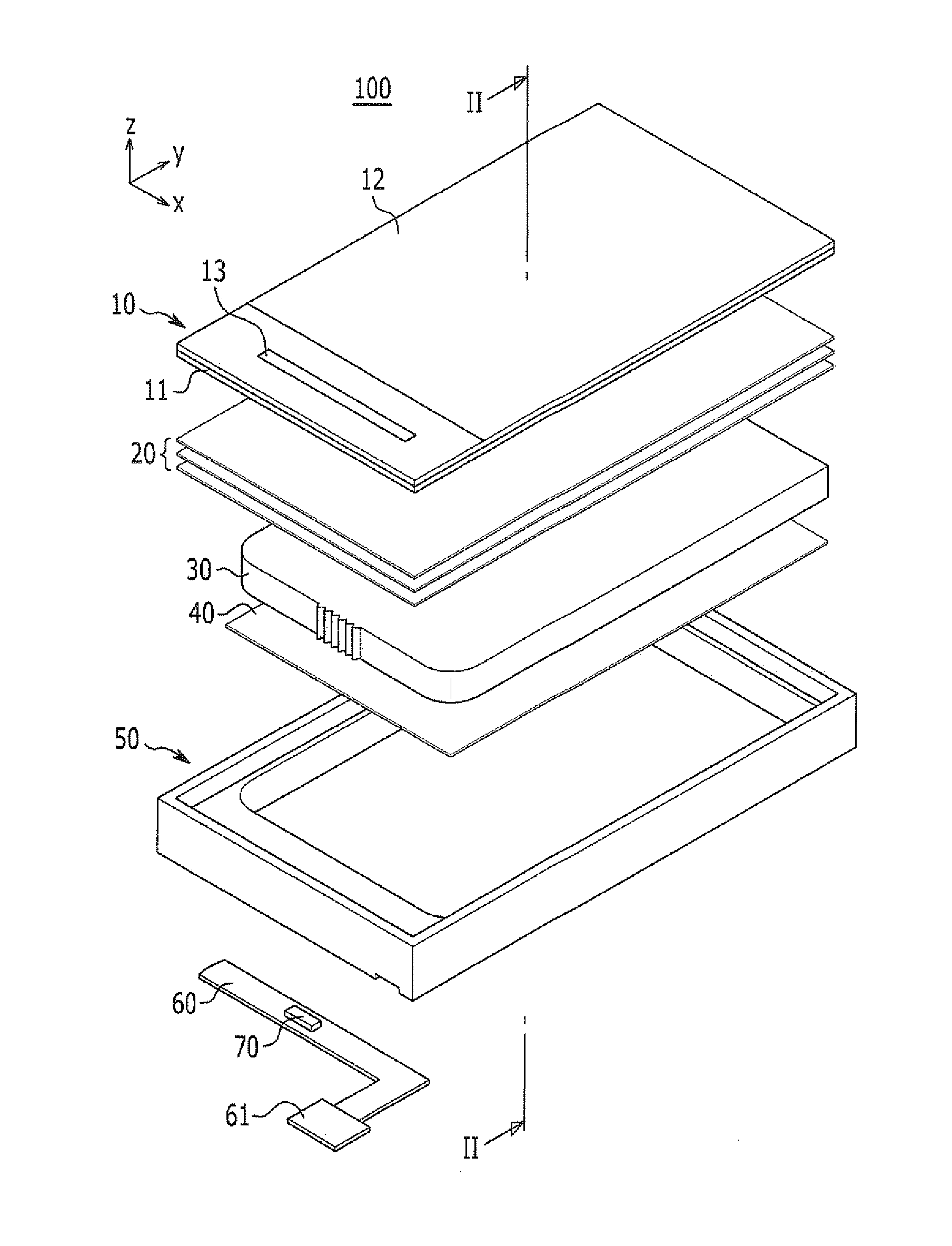
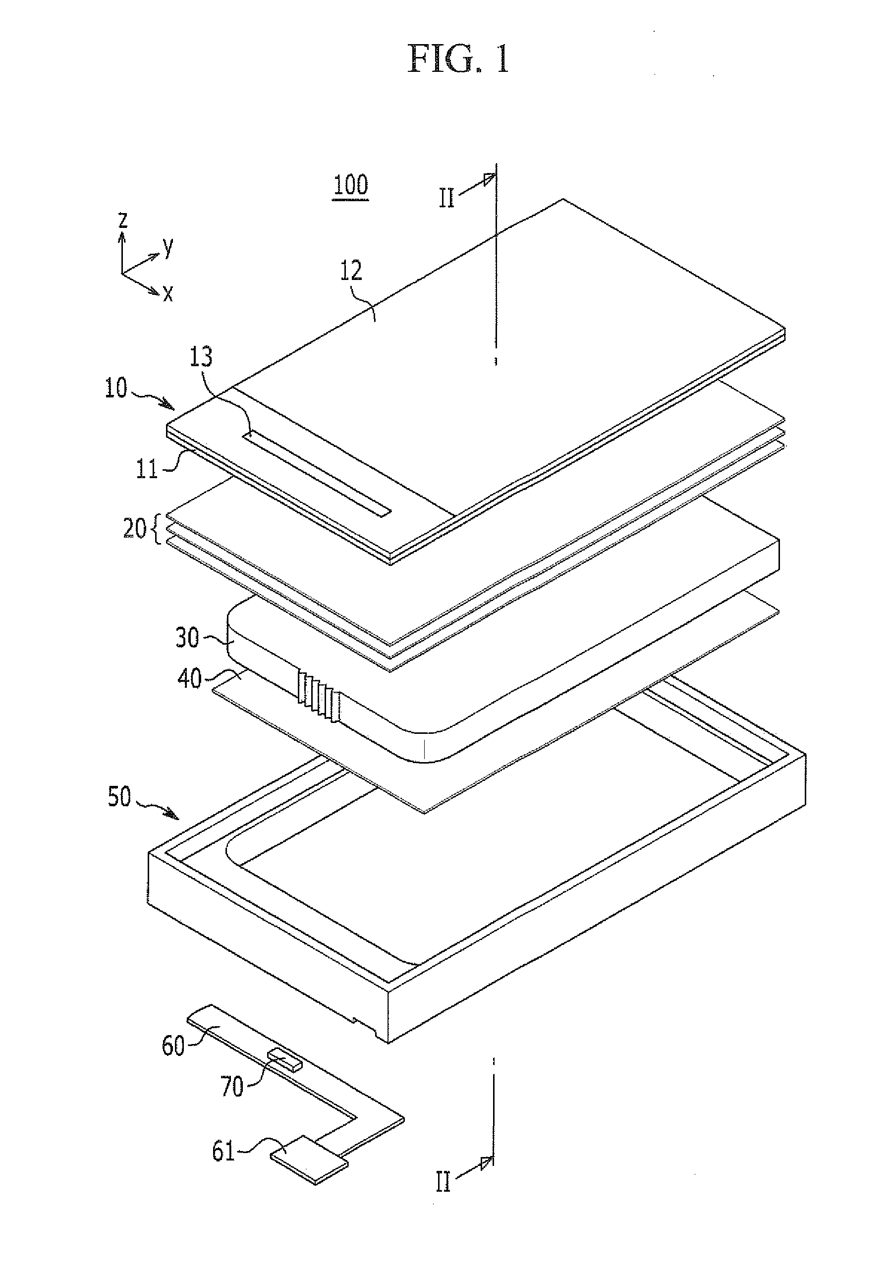
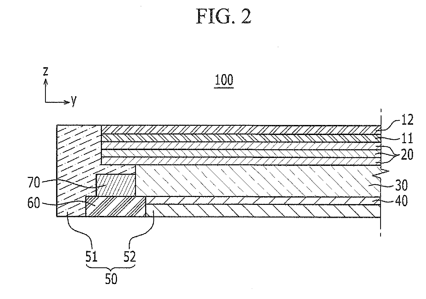
[0043]FIG. 1 is a schematic exploded perspective view of a liquid crystal display (LCD) according to a first exemplary embodiment of the invention, and FIG. 2 is a cross-sectional view of the liquid crystal display (LCD) according to the first exemplary embodiment of the invention, taken along the line II-II of FIG. 1.
[0044]Referring to FIG. 1 and FIG. 2, a liquid crystal display (LCD) 100 according to the first exemplary embodiment of the invention include...
PUM
 Abstract
Description
Claims
Application Information
PatSnap Eureka turns technology decisions into work you can execute. Powered by our Innovation Knowledge Graph, it runs expert workflows across engineering, life sciences, materials and intellectual property. Get your review-ready output in minutes.


