
Reverse time migration back-scattering noise removal using decomposed wavefield directivity

a wavefield directivity and reverse time migration technology, applied in the field of removing backscattering noise, can solve the problems of blurred parts of an image of a subsurface region, unsatisfactory backscattering noise, and smear structural images

Inactive Publication Date: 2012-03-01
CHEVROU USA INC
View PDF5 Cites 51 Cited by
  • Summary
  • Abstract
  • Description
  • Claims
  • Application Information

AI Technical Summary

Benefits of technology

[0005]One aspect of the disclosure relates to a computer-implemented method for generating images of a subsurface region. The method may include decomposing two or more wavefields to produce two or more corresponding decomposed wavefields. The two or more wavefields may include a source wavefield and a receiver wavefield. The method may include determining directivity of the two or more decomposed wavefields to produce corresponding direction-dependent components of the two or more decomposed wavefields. The method may include cross-correlating one or more of the direction-dependent components of one or more decomposed source wavefields with one or more of the direction-dependent components of one or more decomposed receiver wavefields. The method may include generating an image of the subsurface region based on the cross-correlation.
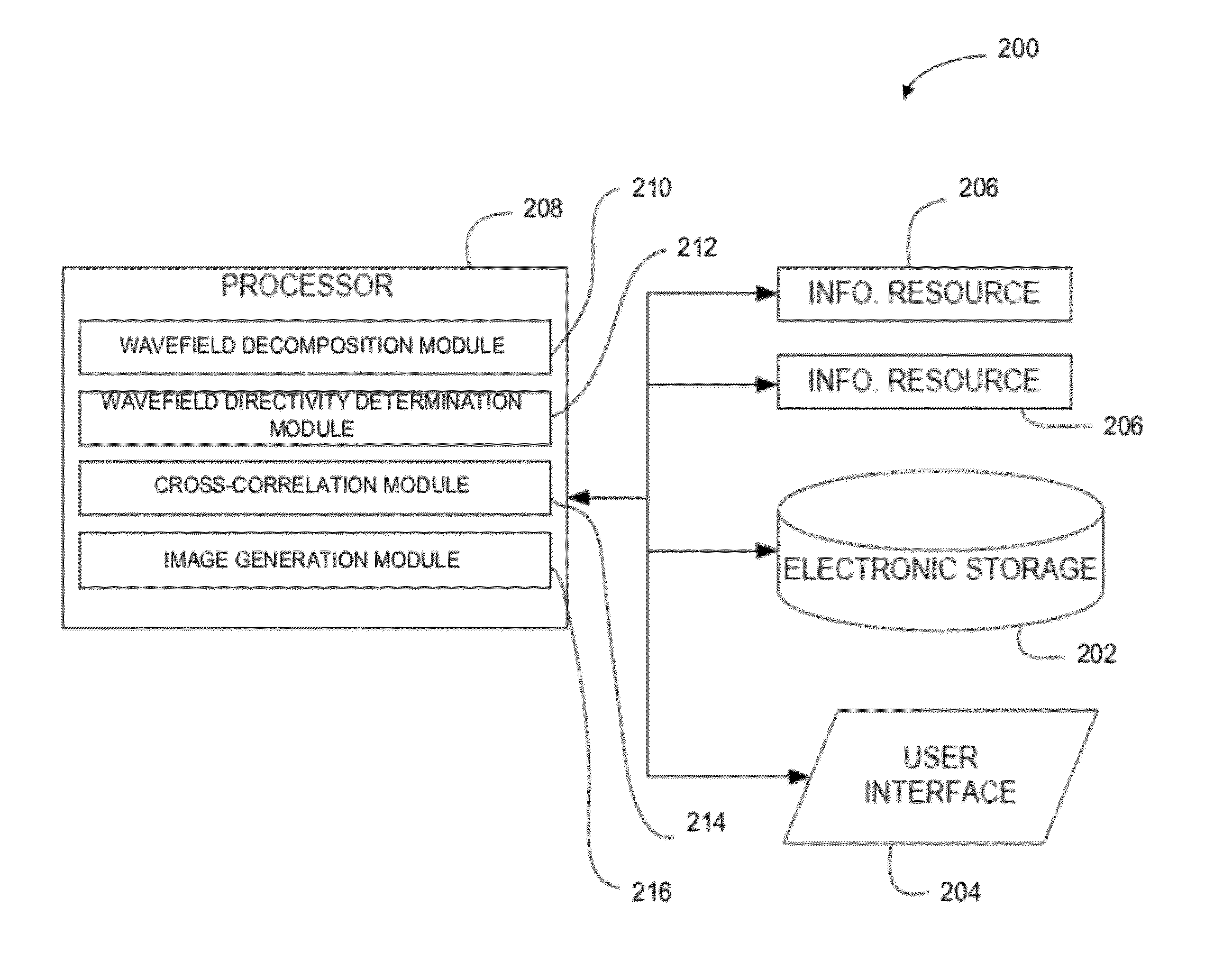
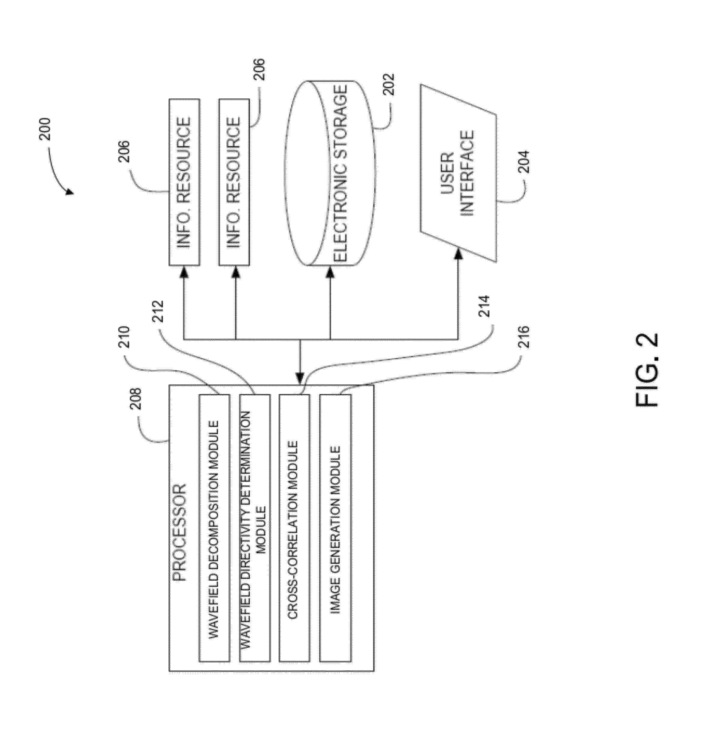
[0006]Another aspect of the disclosure relates to a system configured to generate images of a subsurface region. The system may include one or more processors configured to execute computer program modules. The computer program modules may include a wavefield decomposition module, a wavefield directivity determination module, a cross-correlation module, an image generation module, and/or other modules. The wavefield decomposition module may be configured to decompose two or more wavefields to produce two or more corresponding decomposed wavefields. The two or more wavefields may include a source wavefield or a receiver wavefield. The wavefield directivity determination module may be configured to determine directivity of the two or more decomposed wavefields to produce corresponding direction-dependent components of the two or more decomposed wavefields. The cross-correlation module may be configured to cross-correlate one or more of the direction-dependent components of one or more decomposed source wavefields with one or more of the direction-dependent components of one or more decomposed receiver wavefields.

Problems solved by technology

Application of conventional imaging conditions in reverse time migration upon head waves or turning waves can result in undesired backscattering noise (e.g., low-wave-number artifacts) at some image locations such as above strong impedance contracts.
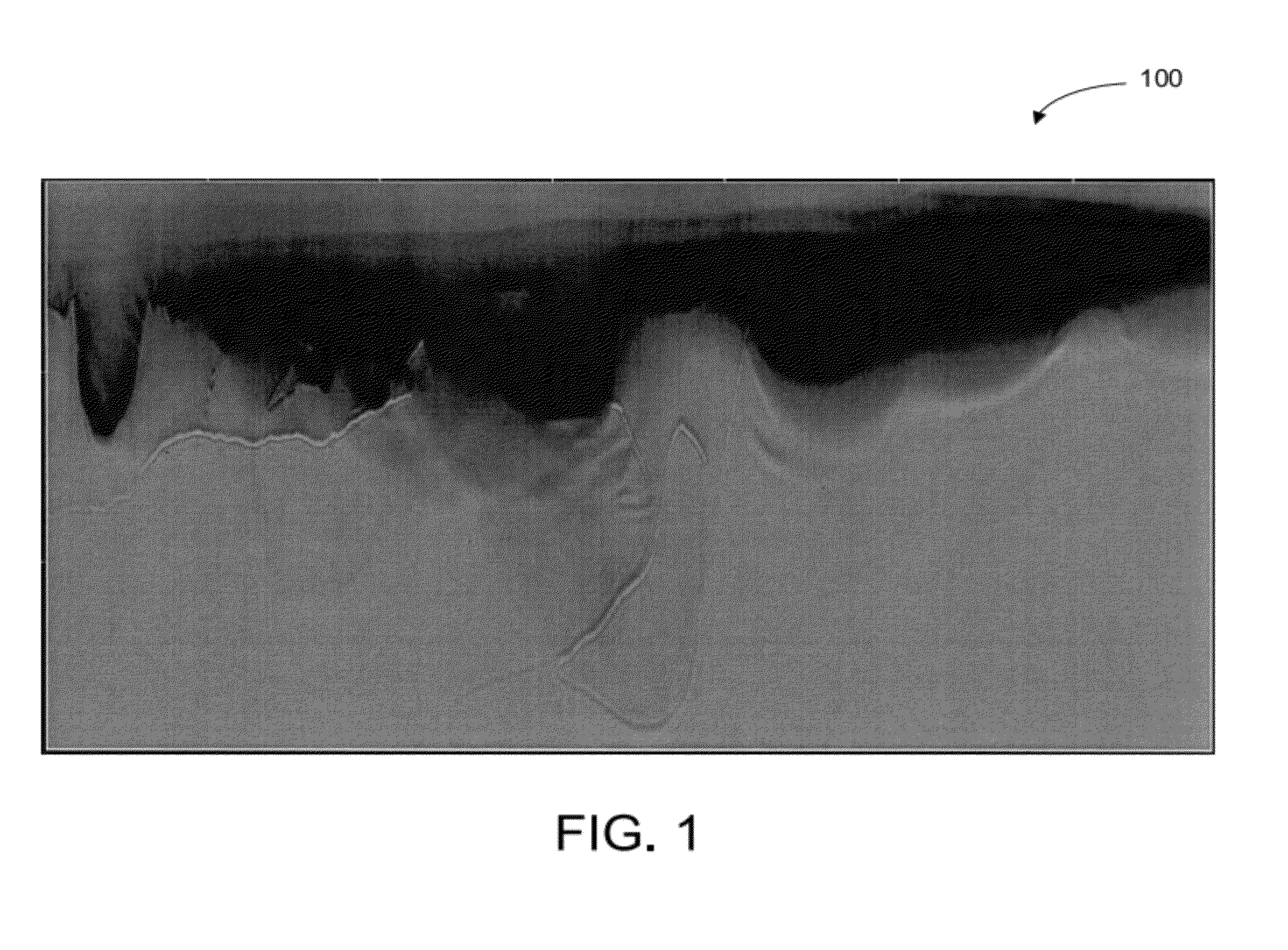
This backscattering noise may lead to blurred portions of an image of a subsurface region.
Such backscattering noise tends to smear structural images and make interpretation above strong reflectors difficult.
Conventional approaches that involve modifying imaging conditions have major limitations for practical use due, for example, to over-restrictiveness, computation costliness, and / or vulnerability to the presence of crossing events.
Conventional approaches that involve image filtering compromise true amplitude processing and, furthermore, the degree of effectiveness of these approaches is dependent on structural complexity, model specifics, and acquisition settings.

Method used


Image

  • Reverse time migration back-scattering noise removal using decomposed wavefield directivity
  • Reverse time migration back-scattering noise removal using decomposed wavefield directivity
  • Reverse time migration back-scattering noise removal using decomposed wavefield directivity

Examples


Embodiment Construction

[0014]The present technology may be described and implemented in the general context of a system and computer methods to be executed by a computer. Such computer-executable instructions may include programs, routines, objects, components, data structures, and computer software technologies that can be used to perform particular tasks and process abstract data types. Software implementations of the present technology may be coded in different languages for application in a variety of computing platforms and environments. It will be appreciated that the scope and underlying principles of the present technology are not limited to any particular computer software technology.

[0015]Moreover, those skilled in the art will appreciate that the present technology may be practiced using any one or combination of hardware and software configurations, including but not limited to a system having single and / or multi-processor computer processors system, hand-held devices, programmable consumer el...


PUM


Abstract

Images of a subsurface region may be generated in conjunction with reverse time migration with reduced or no backscattering noise. Two or more wavefields may be decomposed to produce two or more corresponding decomposed wavefields. The two or more decomposed wavefields may include a source wavefield and a receiver wavefield. Directivity of the two or more decomposed wavefields may be determined to produce corresponding direction-dependent components of the two or more decomposed wavefields. One or more of the direction-dependent components of one or more decomposed source wavefields may be cross-correlated with one or more of the direction-dependent components of one or more corresponding decomposed receiver wavefields. An image of the subsurface region may be generated based on the cross-correlation.

Description

FIELD OF THE DISCLOSURE[0001]The disclosure relates to removing back-scattering noise in reverse time migration using decomposed wavefield directivity for generating images of a subsurface region.BACKGROUND OF THE DISCLOSURE[0002]Images of a subsurface region of Earth can be generated using seismic waves. Seismic waves from one or more wave sources (i.e., source wavefields) at or near Earth's surface propagate through an adjacent subsurface region and are reflected or scattered by interfaces between geological features (e.g., layers having different compositions and / or propagation properties) back to the surface. The reflected or scattered waves are received by one or more wave receivers (i.e., receiver wavefields). The source and receiver waves can then be used to generate images of the subsurface region. This kind of source and receiver correlation imaging condition can be applied to various acquisition geometries, such as, surface source-receiver geometries, vertical seismic prof...

Claims


Application Information

Patent Timeline
IPC IPC(8): G01V1/28
CPCG01V1/28G01V2210/30G01V2210/679G01V2210/67G01V2210/51
Inventor LIU, WEI
Owner CHEVROU USA INC
Learn More