
Terminal elements for coupling connecting rods and control rods in control rod assemblies for a nuclear reactor

a technology of terminal elements and connecting rods, which is applied in the fields of nuclear elements, nuclear power reactor arts, nuclear reaction control apparatus arts, etc., can solve the problem of limited use of such cross-members

Active Publication Date: 2012-03-01
BWXT MPOWER INC
View PDF1 Cites 38 Cited by
  • Summary
  • Abstract
  • Description
  • Claims
  • Application Information

AI Technical Summary

Benefits of technology

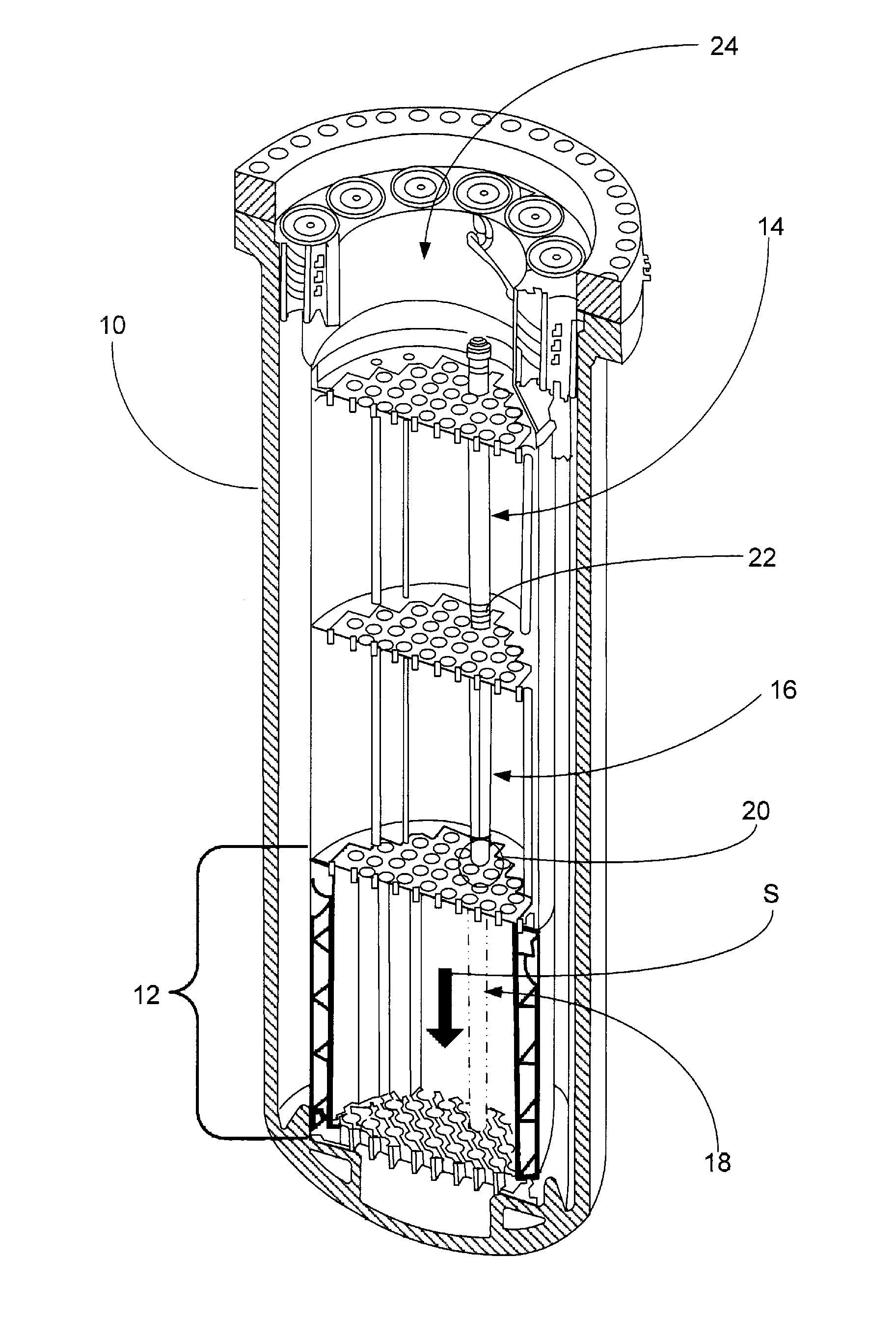
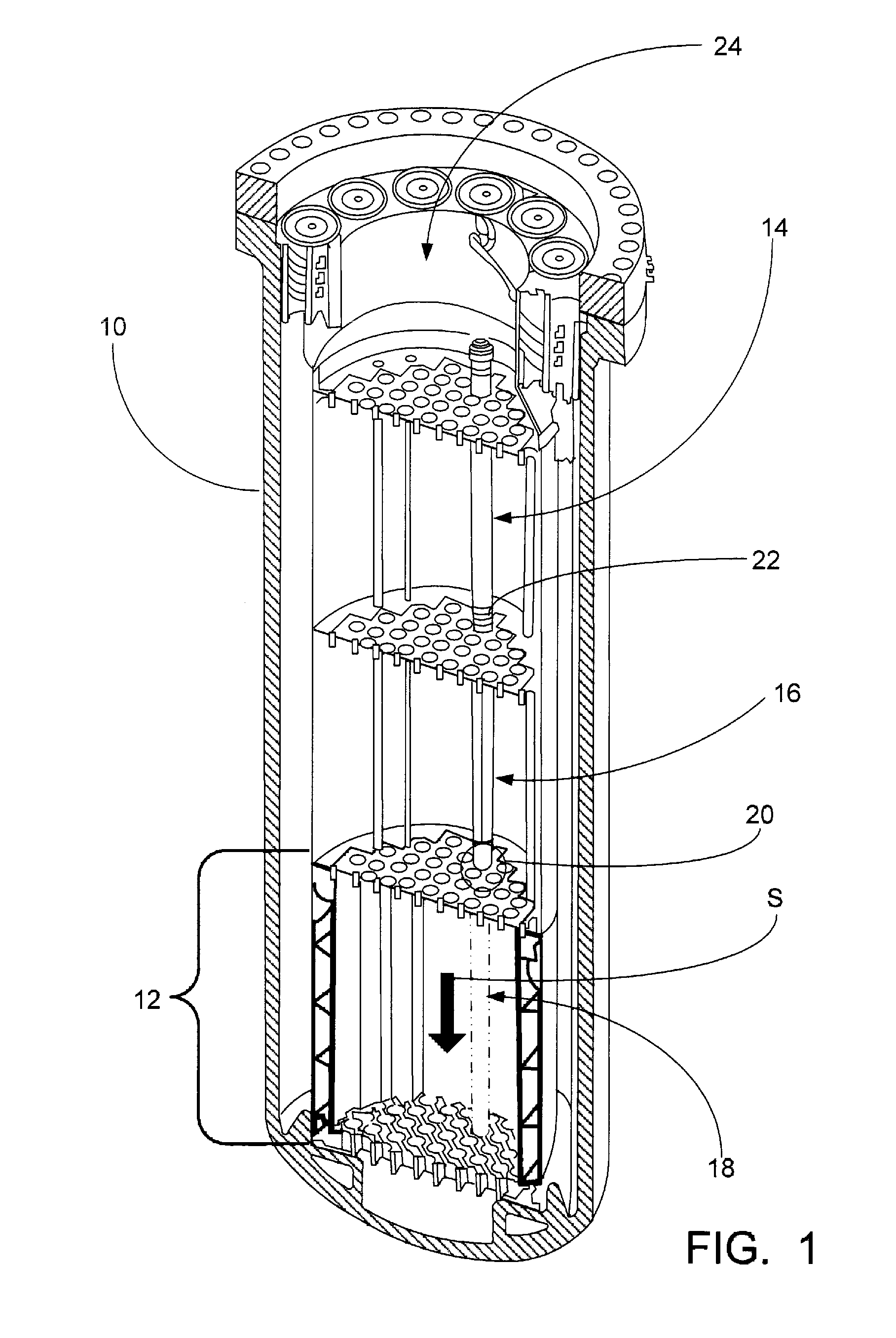
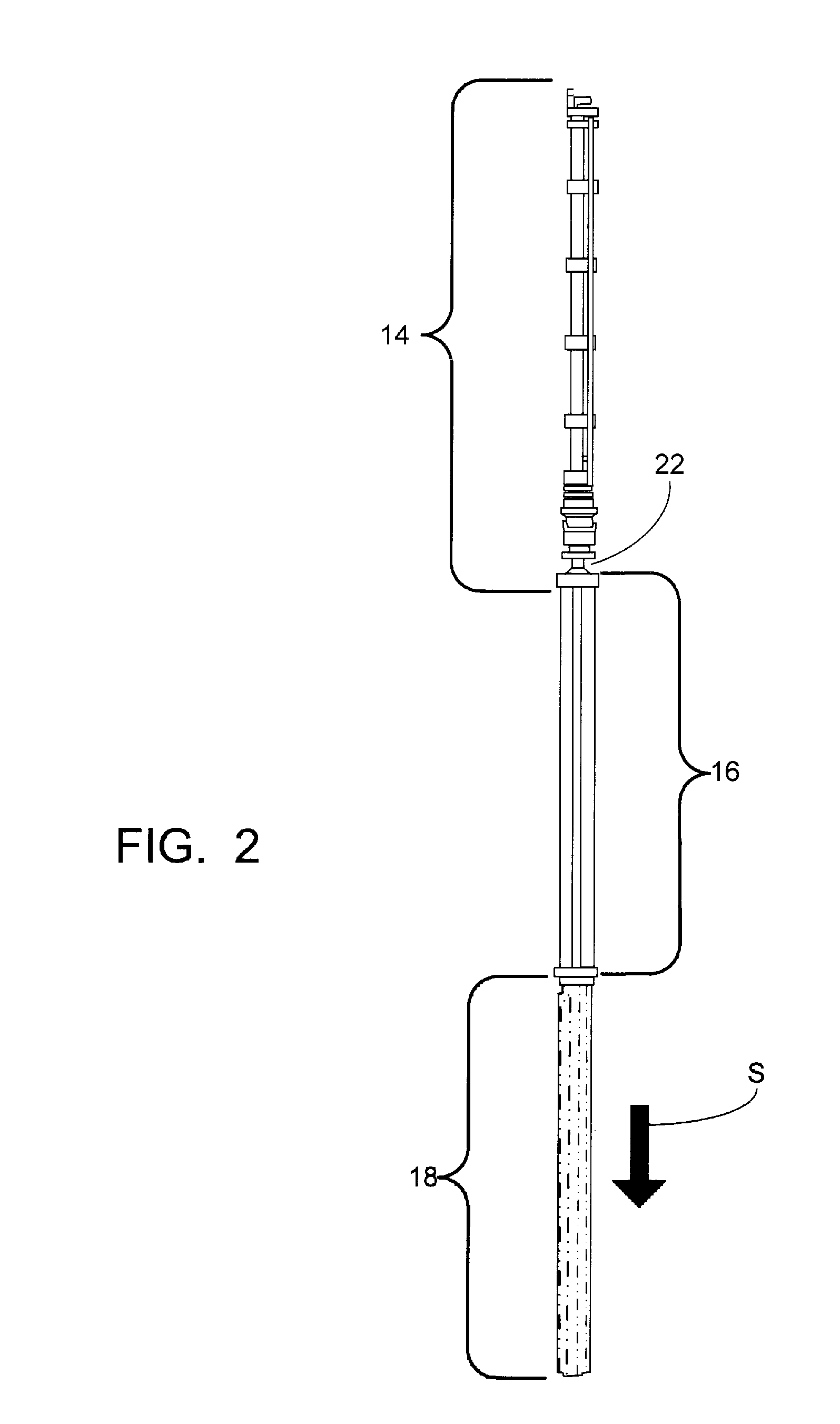
The patent text describes a control rod / control rod drive mechanism (CRDM) coupling that includes a connecting rod and a terminal element. The terminal element is connected to the lower end of the connecting rod and includes a casing and a filler material. The filler material is heavy material that has a higher density than the casing. The terminal element is further connected with an upper end of at least one control rod. The technical effect of this design is that it provides improved control rod functionality and shutdown rod control functionality in a nuclear reactor. Additionally, the terminal element is designed to have a higher density than the casing, which helps to improve the overall performance of the CRDM coupling.

Problems solved by technology

Another limitation on the spider's effective area is that during a SCRAM the spider should not present a large hydraulic resistance that limits acceleration of the detached control rod / spider / connecting rod / (and, optionally, lead screw) assembly toward the reactor core during a SCRAM.
In some spiders, additional supporting cross-members may be provided between the radially extending tubes, but the use of such cross-members is limited by the desire to minimize the actual area oriented broadside to the SCRAM direction.

Method used


Image

  • Terminal elements for coupling connecting rods and control rods in control rod assemblies for a nuclear reactor
  • Terminal elements for coupling connecting rods and control rods in control rod assemblies for a nuclear reactor
  • Terminal elements for coupling connecting rods and control rods in control rod assemblies for a nuclear reactor

Examples


Embodiment Construction

[0028]Disclosed herein is a paradigm shift in control rod / CRDM coupling assemblies. In existing control rod / CRDM coupling assemblies, the control rod is terminated by a lightweight, “spidery” spider having a minimal weight and surface area oriented broadside to the SCRAM direction. The spider is configured to provide a large “effective” area for attachment of control rods, but a small “actual” area contributing to hydraulic resistance during SCRAM. Both the spider and the connecting rod are stainless steel components so as to provide benefits such as strength and robustness, low cost, manufacturability, and compatibility with the reactor vessel environment.

[0029]Disclosed herein are control rod / CRDM coupling assemblies that include one or both of the following aspects: (i) replacement of the conventional lightweight spider with a terminal weighting element, and / or (ii) replacement of a substantial portion of the stainless steel of the control rod / CRDM coupling assembly with a denser...


PUM


Abstract

A nuclear reactor includes a pressure vessel, and a control rod assembly (CRA) including at least one movable control rod, a control rod drive mechanism (CRDM) for controlling movement of the at least one control rod, and a coupling operatively connecting the at least one control rod and the CRDM. The coupling includes a connecting rod engaged with the CRDM and a terminal element connected with a lower end of the connecting rod and further connected with the at least one control rod. In some embodiments the terminal element includes a first portion comprising a first material having a first density and a second portion comprising a second material having a second density that is greater than the first density. In some embodiments the terminal element has a largest dimension parallel with the connecting rod that is greater than or equal to a largest dimension transverse to the connecting rod.

Description

BACKGROUND[0001]The following relates to the nuclear power reactor arts, nuclear reaction control apparatus arts, control rod assembly arts, and related arts.[0002]In known nuclear power plants, a nuclear reactor core comprises a fissile material having size and composition selected to support a desired nuclear fission chain reaction. To moderate the reaction, a neutron absorbing medium may be provided, such as light water (H2O) in the case of light water reactors, or heavy water (D2O) in the case of heavy water reactors. It is further known to control or stop the reaction by inserting “control rods” comprising a neutron-absorbing material into aligned passages within the reactor core. When inserted, the control rods absorb neutrons so as to slow or stop the chain reaction.[0003]The control rods are operated by control rod drive mechanisms (CRDMs). In so-called “gray” control rods, the insertion of the control rods is continuously adjustable so as to provide continuously adjustable ...

Claims


Application Information

Patent Timeline
Patent Type & Authority Applications(United States)
IPC IPC(8): G21C7/06
CPCG21C7/117G21C7/12Y02E30/39G21C9/02Y02E30/30
Inventor SHARGOTS, SCOTT J.ALES, MATHEW W.
Owner BWXT MPOWER INC
Learn More