Blow Mold

a mold and blow mold technology, applied in the field of blow molds, can solve the problems of mold parting plane undetected, mold parts can be damaged, etc., and achieve the effect of quick movemen

Inactive Publication Date: 2012-03-01
KRONES AG
View PDF10 Cites 12 Cited by
  • Summary
  • Abstract
  • Description
  • Claims
  • Application Information

AI Technical Summary

Benefits of technology

[0006]One aspect of the disclosure is to improve a blow mold of this kind such that the mold parts are locked and supported during the blow molding process in a different manner, that a compact design of the blow mold can be achieved, that small masses can be quickly moved, that even great forces are completely withstood during the blow molding process, and that motion drives having small dimensions can be employed for the locking function.
[0007]Being of an extremely low weight and having compact dimensions, the at least one locking sleeve manufactured using high-strength fiber material produces an extreme tensile strength and builds up the locking pressure uniformly across the whole periphery of the mold support shells and essentially the complete height of the mold cavity. Compared to mold support and locking means known up to now, the locking sleeve requires very little assembly space, which desirably permits a very dense arrangement of several blow molding stations on a blow rotor of a blow molding machine. Due to the small mass of the locking sleeve, a motion drive having small dimensions and only moderate power can be used, furthermore saving assembly space and nevertheless ensuring quick cycle times. The at least one locking sleeve is manufactured in a way e.g. similar to vehicle body components in automobile racing and, due to the material-specific high strength, needs an only relatively small wall thickness.

Problems solved by technology

As the locking pressure of the collar acts upon the two mold support shells only in locally restricted areas, there is a risk in that uncontrollable deformations arise at the mold parts under the forces resulting from the blow molding process, whereby the mold parting plane can undesirably show at least in some areas in the manufactured container.

Method used


Image

  • Blow Mold
  • Blow Mold
  • Blow Mold

Examples


Embodiment Construction

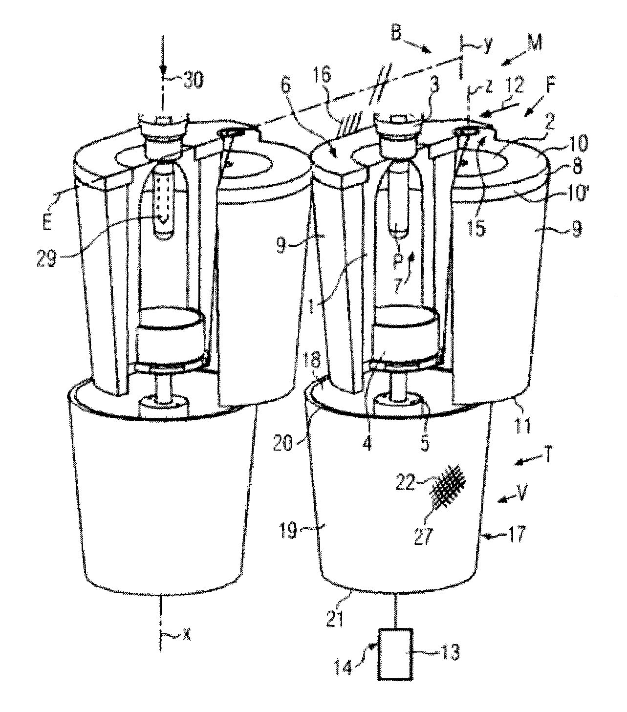
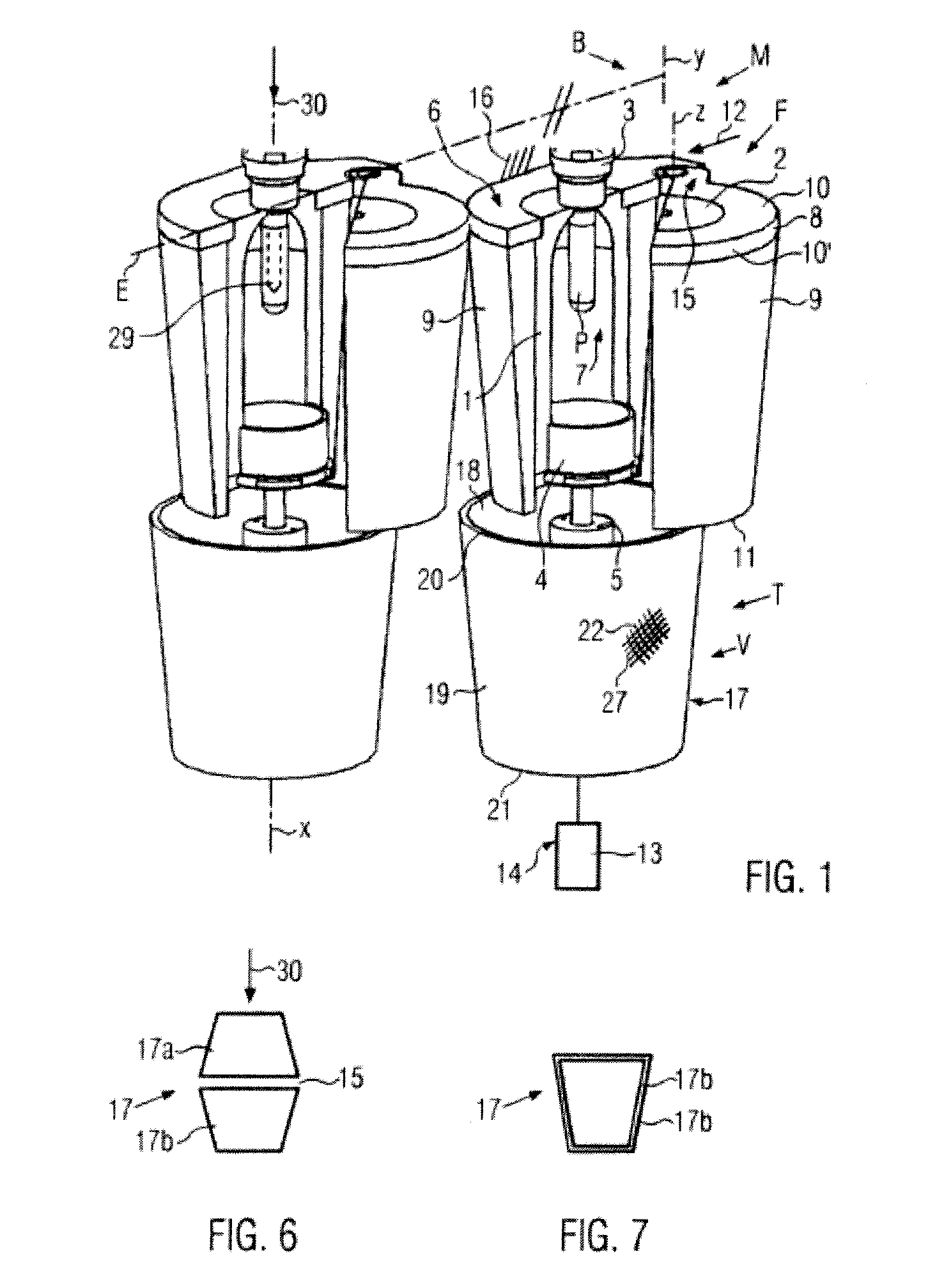
[0031]FIG. 1 shows opened blow molds F provided at adjacent blow molding stations of a blow rotor B of a blow molding machine M. The blow rotor B can be rotationally driven about a blow rotor axis Y. The blow molds F comprise mold parting planes E which are arranged radially to the blow rotor axis Y in the shown embodiment. Each blow mold has a blow mold axis X. As an alternative, the blow molds could be used in stationary blow molding stations of a blow molding machine. Each blow mold F serves, for example, the manufacture of containers from preforms P, for example plastic bottles, by a blow molding process or a stretch-blow molding process, where an opened blow mold is charged with a preform P, closed and locked before the blow molding process runs, and is then opened to be able to remove the produced container.

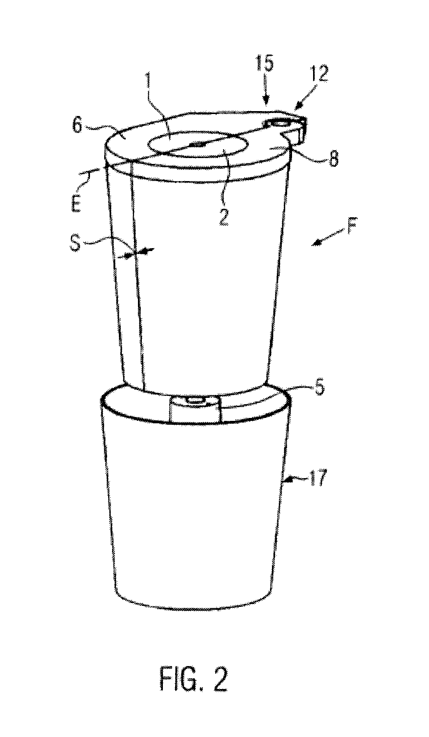
[0032]In the shown embodiment, the blow mold comprises mold parts 1, 2, mainly for forming the container walls, and a mold part 4 as a bottom mold for molding the bottom. T...


PUM

PropertyMeasurementUnit
distanceaaaaaaaaaa
pressureaaaaaaaaaa
strengthaaaaaaaaaa

Abstract

A blow mold having at least two mold parts, mold support shells containing the mold parts, a mold support at least for supporting the mold support shells, motion drives for opening and closing the blow mold, and a locking means adjustable at least in the direction of the mold cavity axis relative to the mold support shells for locking the closed blow mold and for supporting the mold parts against forces from the blow molding process. The locking means has at least one locking sleeve with an at least conical inner wall manufactured using high-strength fiber material, which can be slid with the inner wall onto conical outer surface areas of the mold support shells and supports the mold parts across essentially the complete height of the mold cavity in a locking manner.

Description

CROSS-REFERENCE TO RELATED APPLICATION[0001]The present application claims the benefit of priority of German Application No. 102010040004.1 filed Aug. 31, 2011. The entire text of the priority application is incorporated herein by reference in its entirety.FIELD OF THE DISCLOSURE[0002]The disclosure relates to a blow mold such as of the type used in forming containers.BACKGROUND[0003]In blow molding or stretch-blow molding, at least the mold parts (mold halves) forming the wall regions of the container are usually received in mold support shells. The mold support shells normally also fulfill the function of controlling the temperature of the blow mold. To this end, channels through which a temperature control medium (water, oil) flows can be formed in the mold support shells. A usually two-part mold support is provided for fixing the mold support shells, the mold support producing the retaining function for the mold support shells and primarily serving to withstand the forces during...

Claims


Application Information

Patent Timeline
Patent Type & Authority Applications(United States)
IPC IPC(8): B29C49/48B29C49/56B29C33/02B29C49/28
CPCB29C49/56B29C33/26B29C49/36B29C2049/1252B29C49/4236B29C49/4823B29C2049/4892B29C49/42B29C49/122B29C2049/5633B29C2049/5635B29C2049/5661
Inventor STOIBER, CHRISTIANALBRECHT, THOMAS
Owner KRONES AG
Why Eureka
Try Eureka