Electrical connector

a technology of electrical connectors and connectors, applied in the direction of coupling device connections, coupling protective earth/shielding arrangements, electrical apparatus, etc., can solve the problems of affecting the appearance of products, difficult to assemble connectors, and inconvenient soldering of connectors, so as to improve assembly accuracy and simplify the soldering process

Inactive Publication Date: 2012-03-01
CHENG UEI PRECISION IND CO LTD
View PDF2 Cites 6 Cited by
  • Summary
  • Abstract
  • Description
  • Claims
  • Application Information

AI Technical Summary

Benefits of technology

[0006]As described above, at least one the positioning block divides the insulating housing into several parts. The positioning block cooperates with the shielding shell to form several receiving spaces for receiving plug connecto

Problems solved by technology

However, it is inconvenient to solder the connectors one by one, and it is also difficult to assemble the connectors at certain positio

Method used


Image

  • Electrical connector
  • Electrical connector
  • Electrical connector

Examples


Embodiment Construction

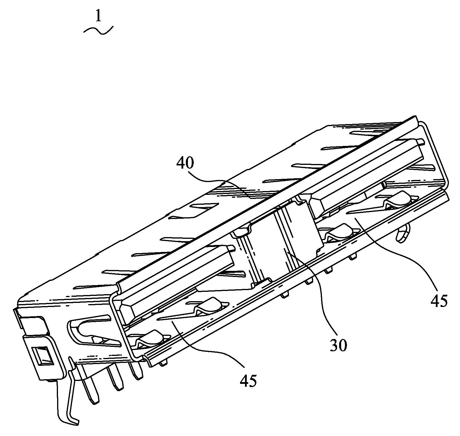
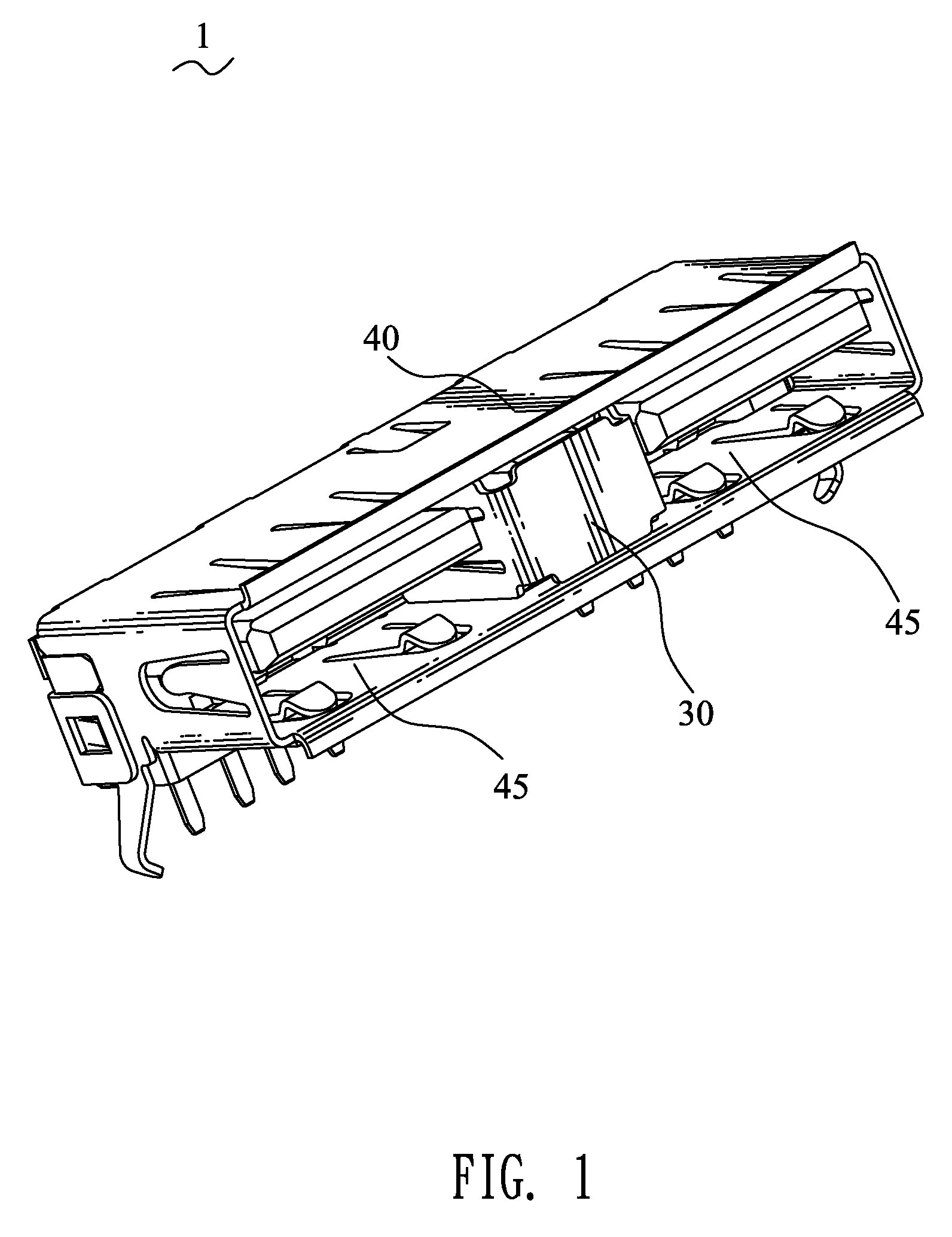
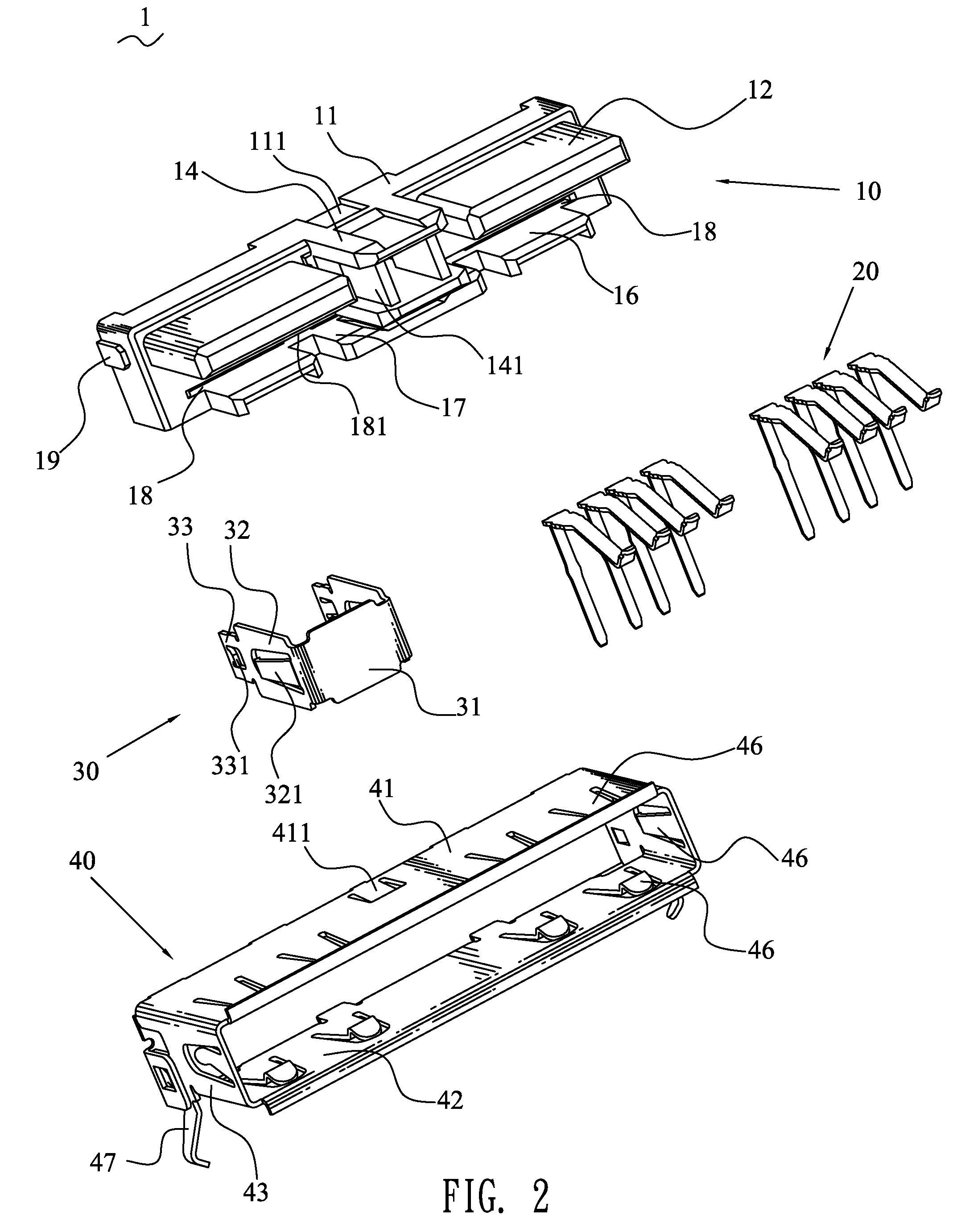
[0013]Referring to the drawings in greater detail, and first to FIGS. 1-2, the embodiment of the invention is embodied in an electrical connector 1. The electrical connector 1 includes an insulating housing 10, a plurality of terminals 20 mounted into the insulating housing 10, a connecting element 30 fixed on the insulating housing 10, a shielding shell 40 covering the insulating housing 10.

[0014]With reference to FIGS. 2-4, the insulating housing 10 has a rectangular base 11. A top side of the base 11 is recessed to form a buckling recess 111 with a close end adjacent to a front surface of the base 11. The base 11 has a rectangular positioning block 14 protruded from a middle of the front surface thereof. A top of the positioning block 14 is level with that of the base 11. Two lateral sides of the positioning block 14 are recessed to form receiving recesses 141 at a substantially middle portion thereof. The positioning block 14 divides the front surface of the base 11 into two par...


PUM


Abstract

An electrical connector has an insulating housing. The insulating housing has a base. At least one positioning block is protruded from a front of the base and separates the base into several equal parts. A plurality of terminals is mounted into the insulating housing. A connecting element is fixed on the positioning block. A shielding shell wraps the insulating housing. The positioning block cooperates with the shielding shell to form receiving spaces for receiving plug connectors. So, the electrical connector is capable of receiving multiple plug connectors. Meanwhile, the electrical connector simplifies the soldering process while assembling multiple connectors, and also, improves the assembly accuracy.

Description

BACKGROUND OF THE INVENTION[0001]1. Field of the Invention[0002]The present invention relates to an electrical connector, and particularly to an electrical connector capable of receiving multiple plug connectors.[0003]2. The Related Art[0004]As electrical products need to connect with various external devices, multiple electrical connectors are required on an electrical product. The connectors are usually assembled on the PCB (Printed Circuit Board) one by one as it is convenient in use. However, it is inconvenient to solder the connectors one by one, and it is also difficult to assemble the connectors at certain position. The connectors may be assembled at different height, which greatly influents the appearance of the product and affects customers' use.SUMMARY OF THE INVENTION[0005]Accordingly, an object of the present invention is to provide an electrical connector. The electrical connector has an insulating housing. The insulating housing has a base. At least one positioning blo...

Claims


Application Information

Patent Timeline
IPC IPC(8): H01R13/648
CPCH01R13/6594H01R12/724
Inventor LAI, MING-CHUN
Owner CHENG UEI PRECISION IND CO LTD
Why Eureka
Try Eureka