
Electronic music stand performer subsystems and music communication methodologies

a technology of performer subsystem and performer, applied in the field of music, can solve the problems of complex and costly adaptation or variation of musical arrangements, remote musicians are unable to effectively practice together, and few musicians are limited

Inactive Publication Date: 2012-03-08
OL SECURITY LIABILITY CO
View PDF15 Cites 38 Cited by
  • Summary
  • Abstract
  • Description
  • Claims
  • Application Information

AI Technical Summary

Benefits of technology

The present invention is a system and method for displaying music using an electronic music stand. The system includes a performer subsystem with processing logic, performance logic, and communications management logic. The user input and display can be integrated into a touch-screen display. The system can be used in a linked mode where two performer subsystems work together or in a standalone mode where each subsystem operates independently. The method includes defining music image data, logical sections, and storing the mapping in a memory for selective retrieval. The system also allows users to bookmark and navigate through the music data with ease. The invention provides a quick and user-friendly way to display and annotate music data.

Problems solved by technology

Adaptations or variations of musical arrangements are complex and costly.
Remotely located musicians are unable to effectively practice together.
Small communities each with only a few musicians are limited to practicing with the few musicians they have.
Performers of music have many inconveniences to deal with.
One such inconvenience deals with the composing, distribution, and utilization of music display presentation, traditionally sheet music.
Another major problem relates to the inconvenience of scheduling and physical gathering of multiple musicians (including instrumentalists and vocalists), which when combined in their performance provide a musical ensemble or orchestra.
However, this creates difficulties in that many students have other activities which conflict with band practice which is then incomplete.
This is only of limited help.
Furthermore, the use of paper sheet music is cumbersome and inconvenient; pages often get damaged or lost, and indexed access is poor and slow.
This method of composing and distributing music is inadequate when the music is used by a band or orchestra that requires hundreds of copies.
This is a very costly, time-consuming, and laborious task if the orchestra has a large number of members.
This, again, is a very costly and laborious task if the band has a large number of musicians requiring different parts.

Method used


Image

  • Electronic music stand performer subsystems and music communication methodologies
  • Electronic music stand performer subsystems and music communication methodologies
  • Electronic music stand performer subsystems and music communication methodologies

Examples


Embodiment Construction

[0042]While this invention is susceptible of embodiment in many different forms, there is shown in the drawing, and will be described herein in detail, specific embodiments thereof with the understanding that the present disclosure is to be considered as an exemplification of the principles of the invention and is not intended to limit the invention to the specific embodiments illustrated.

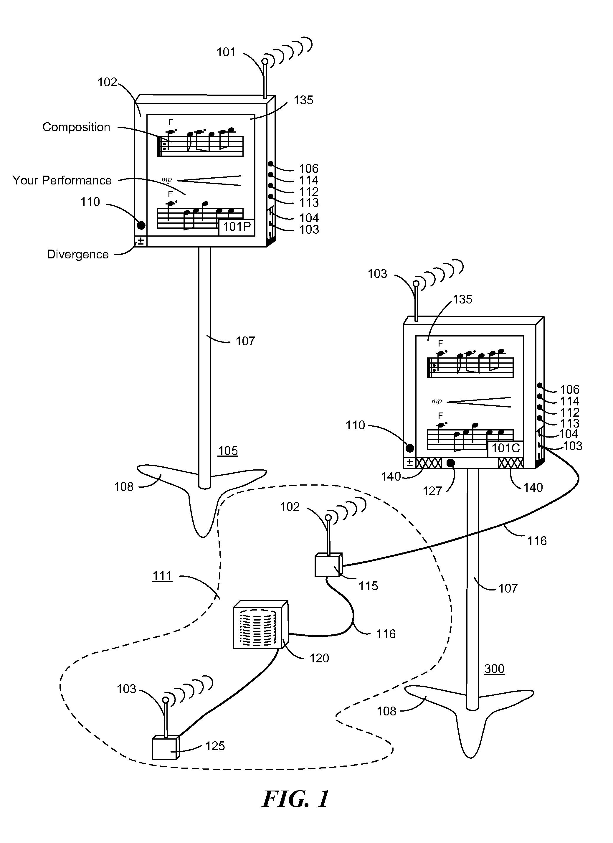
[0043]As illustrated in FIG. 1, a system controller, in the form of a music stand (105) with a liquid crystal display, is used by an operator (e.g., performer, conductor, etc.) to select one or more musical compositions. FIG. 1 illustrates two types of music workstations stands. The workstation stand (105) provides certain optional features for a more full-featured stand, including as illustrated, speakers (140) both wireless and wired communications capability, and as illustrated, shows the processor with memory (115) as an external separate component. The master music stand (300) shows the integr...


PUM


Abstract

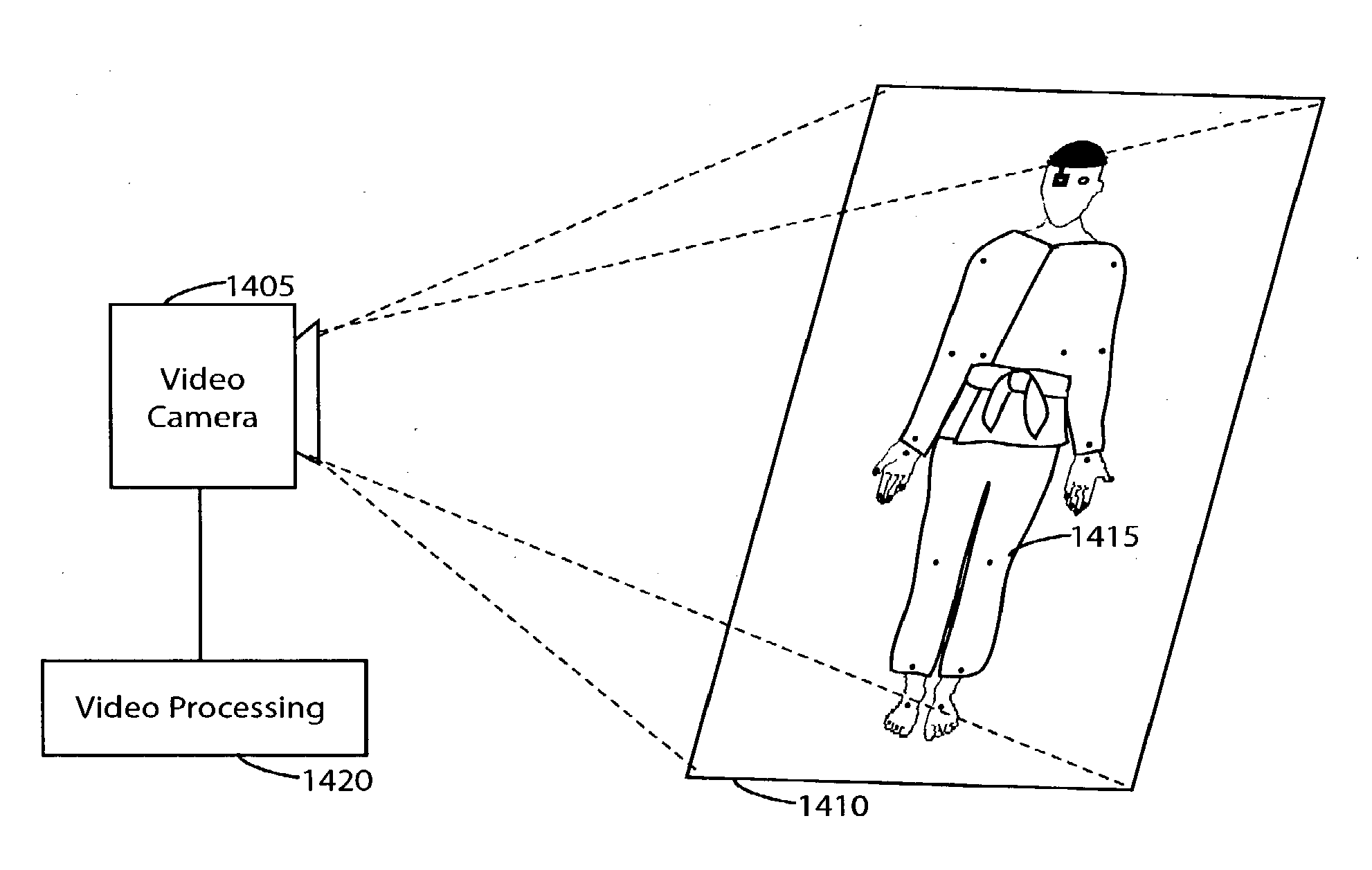
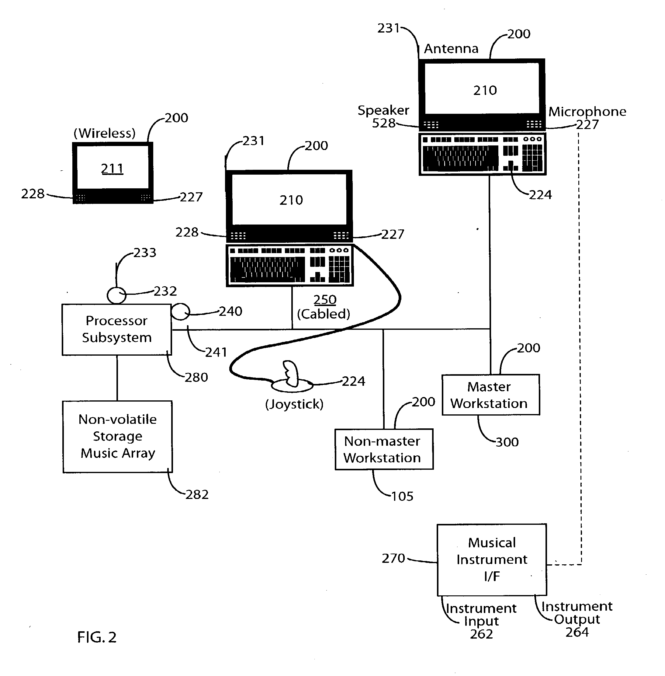
An electronic music stand system and methodologies relating thereto are presented. The electronic music stand system is comprised of a performer subsystem comprising a processing subsystem, librarian logic, performance logic, and communications management logic. The communications management logic provides management of communication via the communications interface with external apparatus responsive to the performance logic and the librarian logic. The user input apparatus and the display apparatus can be integrated into a touch-screen input display. The user input apparatus can alternatively be at least one of a touch-tablet, a stylus-based writing tablet, a mouse, a keyboard, a joystick, a game controller, and a switch. In a preferred embodiment, the librarian logic, the performance logic and the communications management logic are defined by program data stored in the data storage apparatus, and the processor is responsive to the program data for managing data formatting, displaying music, and management of communications of data with the external apparatus. In one embodiment, two Performer subsystems are operable alternatively as one of a single appliance as a linked set a linked mode and as two independent appliances a stand-alone mode, wherein in the linked mode each of the two Performer subsystems operate cooperatively with each other as a linked set to provide a two page display on the video presentation, and wherein in the stand alone mode each of the two Performer subsystems operates independently and mutually exclusive of the other to provide two independent and mutually exclusive single page displays on the video presentation. The present invention also relates to a method for providing for video display of music responsive to the music data stored in a music database. The method is comprised of defining a page of music image data from the music database; defining ordered logical sections; storing the mapping in a memory for selective retrieval; and providing for the video display of the music responsive to the mapping and the storing.

Description

RELATED APPLICATIONS[0001]This is a continuation-in-part application of Ser. No. 09 / 492,218 filed Jan. 27, 2000—a continuation-in-part application of Ser. No. 09 / 039,952 filed Mar. 16, 1998, now issued as U.S. Pat. No. 6,084,168—a continuation-in-part application of Ser. No. 08 / 677,469 filed Jul. 10, 1996, now issued as U.S. Pat. No. 5,728,960.FEDERALLY SPONSORED RESEARCH OR DEVELOPMENT[0002]Not applicable.BACKGROUND OF THE INVENTION[0003]The present invention relates to the field of music. More particularly, the present invention relates to an architecture, system, apparatus and methodology relating to the construction and utilization of a subsystem (or a plurality of subsystems) for displaying musical compositions, either batch or in a real time environment, and processing and communicating music data and / or user performances.[0004]Music is usually only available in the written form for one (or a fixed set of) performer / instrument types in a fixed key. Adaptations or variations of...

Claims


Application Information

Patent Timeline
Patent Type & Authority Applications(United States)
IPC IPC(8): H04N7/18G09B15/02G10G1/00
CPCG09B15/023G10H2220/015G10H1/0008G10G1/00G06F3/1454
Inventor SITRICK, DAVID H.FLING, RUSSELL T.
Owner OL SECURITY LIABILITY CO
Learn More