
Sink drain

Inactive Publication Date: 2012-03-15
CHENG MING TU
View PDF2 Cites 12 Cited by
  • Summary
  • Abstract
  • Description
  • Claims
  • Application Information

AI Technical Summary

Benefits of technology

[0005]The primary object of the present invention is to provide a sink drain which comprises an insertion cap and a base. The insertion cap comprises an elastic telescopic pipe and a stopper disposed on top of the telescopic pipe. The stopper is a flat plate with a washer surrounding a peripheral edge thereof, and cooperates with the telescopic pipe to control drain of water. The insertion cap further comprises a plug seat which extends outward and upward from a bottom of the insertion cap to form an opening facing up. At least one side of the plug seat is provided with a protruding resilient plate. The resilient plate is a curved plate which has an upper curve surface and a lower curve surface. The base comprises a cylindrical body and an annular plate connected with a top edge of the cylindrical body. The base has at least one fixing hole disposed at a central section thereof. The fixing hole is adapted for engagement of the resilient plate of the insertion cap. The insertion cap is inserted in the base and the resilient plate of the plug seat is aligned with and located above the fixing hole of the base. After that, the insertion cap is pressed downward. The resilient plate is subjected to the diameter of the cylindrical body and compressed inward along the lower curve surface to be positioned in the fixing hole, such that the insertion cap is positioned in place. In this way, the stopper can be pressed to control drain of water. The present invention can be disassembled, assembled and cleaned with ease.
[0006]Preferably, the telescopic pipe of the insertion cap can be replaced with a drain pipe which is pulled up by hand. The stopper is pressed to control drain of water. Alternatively, the drain pipe is manually pulled to link the stopper to control drain of water. The sink drain can be used to the drainage hole of a wash sink or a bathtub. When cleaned, the insertion cap is pulled upward. The resilient plate is subjected to the diameter of the cylindrical body and compressed inward along the upper curve surface to be disengaged from the fixing hole, so that the insertion cap can be taken out for cleaning with forceps. The base also can be cleaned with a brush. After cleaning, the insertion cap and the base are easily and quickly assembled again.

Problems solved by technology

However, the diameter of the base is too small, which limits the cleaning.
This is not easy to clean the sink drain.

Method used


Image

  • Sink drain
  • Sink drain
  • Sink drain

Examples


Embodiment Construction

[0013]Embodiments of the present invention will now be described, by way of example only, with reference to the accompanying drawings.

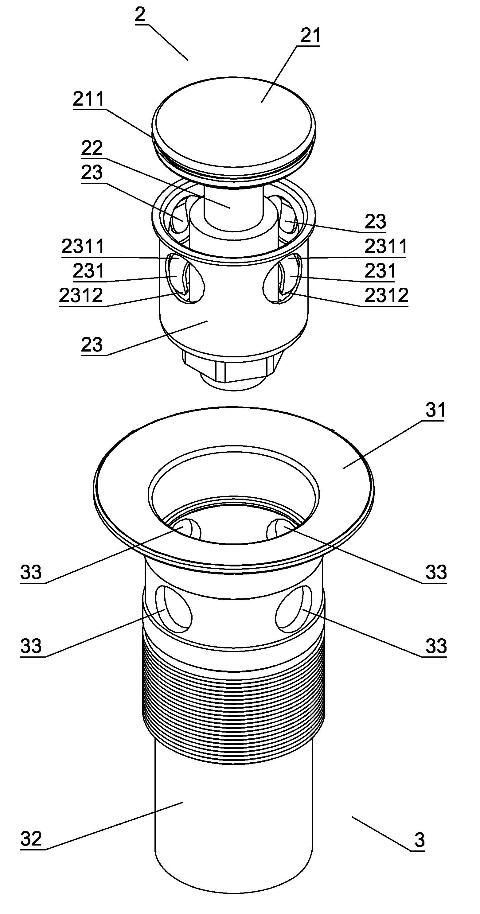
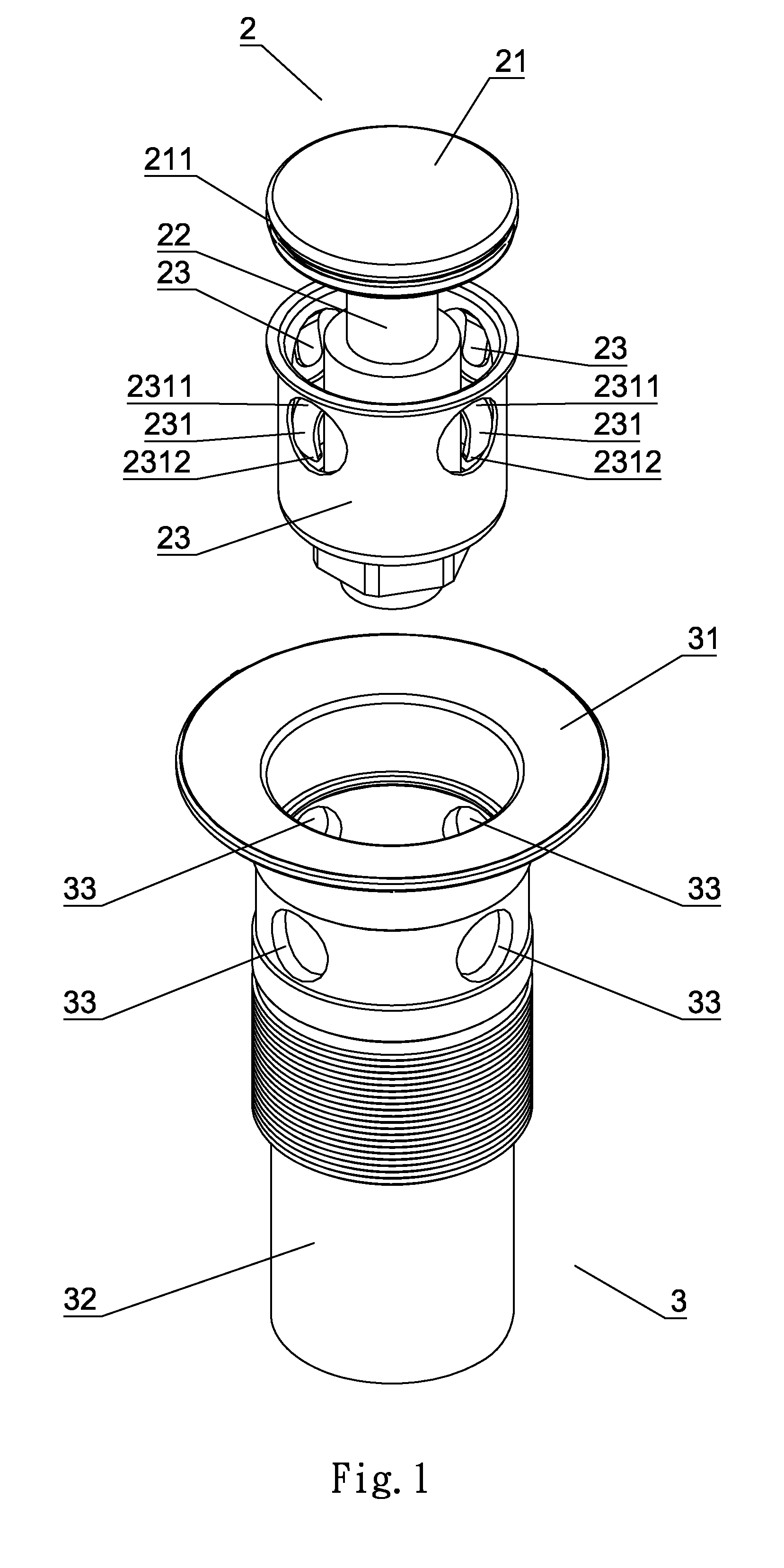
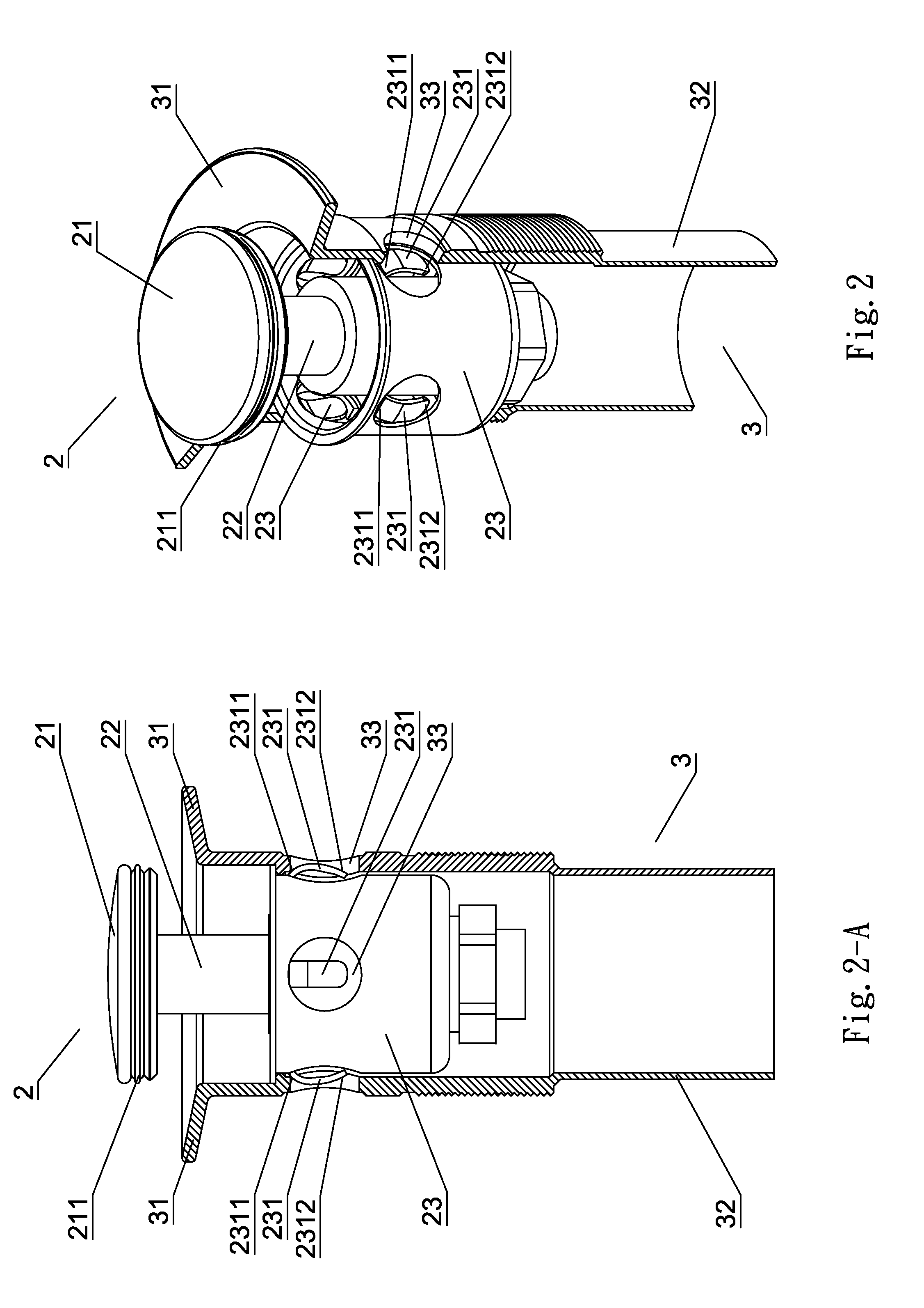
[0014]As shown in FIG. 1, FIG. 3 and FIG. 3-A, the sink drain according to a preferred embodiment of the present invention comprises an insertion cap 2 and a base 3.

[0015]The insertion cap 2 comprises an elastic telescopic pipe 22 and a stopper 21 disposed on top of the telescopic pipe 22. The stopper 22 is a flat plate with a washer 211 surrounding a peripheral edge thereof, and cooperates with the two-section telescopic pipe 22 to control drain of water. The insertion cap 2 further comprises a plug seat 23 which extends outward and upward from a bottom of the insertion cap 2 to form an opening facing up. At least one side of the plug seat 23 is provided with a protruding resilient plate 231. The resilient plate 231 is a curved plate which has an upper curve surface 2311 and a lower curve surface 2312.

[0016]The base 3 comprises a cylindrical body 32 ...


PUM


Abstract

A sink drain includes an insertion cap and a base. The insertion cap includes a plug seat which extends outward and upward from a bottom of an insertion cap to form an opening facing up. At least one side of the plug seat is provided with a protruding resilient plate. The base has at least one fixing hole disposed at a central section thereof. The fixing hole is adapted for engagement of the resilient plate of the insertion cap. When the insertion cap is pressed down or pulled up, the resilient plate is subjected to the diameter of a cylindrical body of the base and compressed inward along the lower curve surface or the upper curve surface to be engaged with or disengaged from the fixing hole, such that the stopper can be pressed to control drain of water.

Description

BACKGROUND OF THE INVENTION[0001]1. Field of the Invention[0002]The present invention relates to a sink drain, and more particularly to one having at least one protruding resilient plate provided on a plug seat of an insertion cap to engage with or disengage from at least one fixing hole of a base. The sink drain can be assembled or disassembled with ease.[0003]2. Description of the Prior Art[0004]A convention sink drain is assembled in the way of threaded positioning or link positioning. The way of threaded positioning uses a cap screwed to an inner threaded hole of a base. The cap is elastically pressed to control drain of water. When cleaned, the cap is unscrewed from the base. However, the diameter of the base is too small, which limits the cleaning. It is necessary to use a specific tool for cleaning. The way of link positioning uses a link rod connected to the bottom of the cap. A lever provided at the back of faucet is to control drain of water. When cleaned, only the cap can...

Claims


Application Information

Patent Timeline
IPC IPC(8): E03C1/23
CPCE03C1/2306
Inventor CHENG, MING-TU
Owner CHENG MING TU
Learn More