Hand-held steam appliances

a steam appliance and hand-held technology, applied in the direction of lighting and heating apparatus, water heaters, textiles and paper, etc., can solve the problems of inability to produce very quickly, low production pressure, and relatively ineffectiveness, and achieve the effect of increasing width, enhancing steam generation efficiency, and maximising surface area

Inactive Publication Date: 2012-03-15
STRIX LTD
View PDF8 Cites 7 Cited by
  • Summary
  • Abstract
  • Description
  • Claims
  • Application Information

AI Technical Summary

Benefits of technology

[0010]Thus it will be seen by those skilled in the art that in accordance with the invention steam can be produced “on demand” in a mobile unit by a user opening the valve to admit water into the boiler, with very little time lag because the water is stored on the mobile unit—i.e. very close to the boiler and is stored under pressure so it will quickly enter the boiler upon the valve being opened.
[0042]In a set of embodiments therefore the base unit and mobile unit comprise means for preventing separation in a direction substantially parallel to the axis of the connection, but which permit removal of the appliance in a direction non-parallel to said axis. In such embodiments the configuration of the base and mobile unit prevent disconnection under the force of the pressurized water supply tending to separate the connectors and / or the contact force of the electrical connector, whilst still allowing the user to remove the mobile unit from the base simply picking it up in an appropriate direction. One possible way of implementing this would be to provide a recess on the base unit into which the appliance could be seated by a tilting or rotating action with the distal wall of the recess, or indeed any other mechanical arrangement, preventing movement along the connector axis, i.e. tangential to the tilting action required to place or remove the mobile unit. Another example would be a hook or ridge on one of the mobile unit or the base unit cooperating with a corresponding feature on the other.

Problems solved by technology

However, the steam produced is at very low pressure (essentially ambient pressure) and cannot be produced very quickly, making it relatively ineffective.
They deliver a very high performance but are very expensive and tend to account therefore only for a very small proportion of the market.
The main disadvantage with these arrangements, commonly known as instantaneous steam generator irons, is that there is in fact a significant time lag (of the order of 10 seconds) between the user pressing a button to demand steam and the steam actually being produced and conveyed to the iron.
This significantly limits user acceptance, even though higher steam flow rates than vented steam irons can be achieved when the steam is eventually delivered.

Method used


Image

  • Hand-held steam appliances
  • Hand-held steam appliances
  • Hand-held steam appliances

Examples


Embodiment Construction

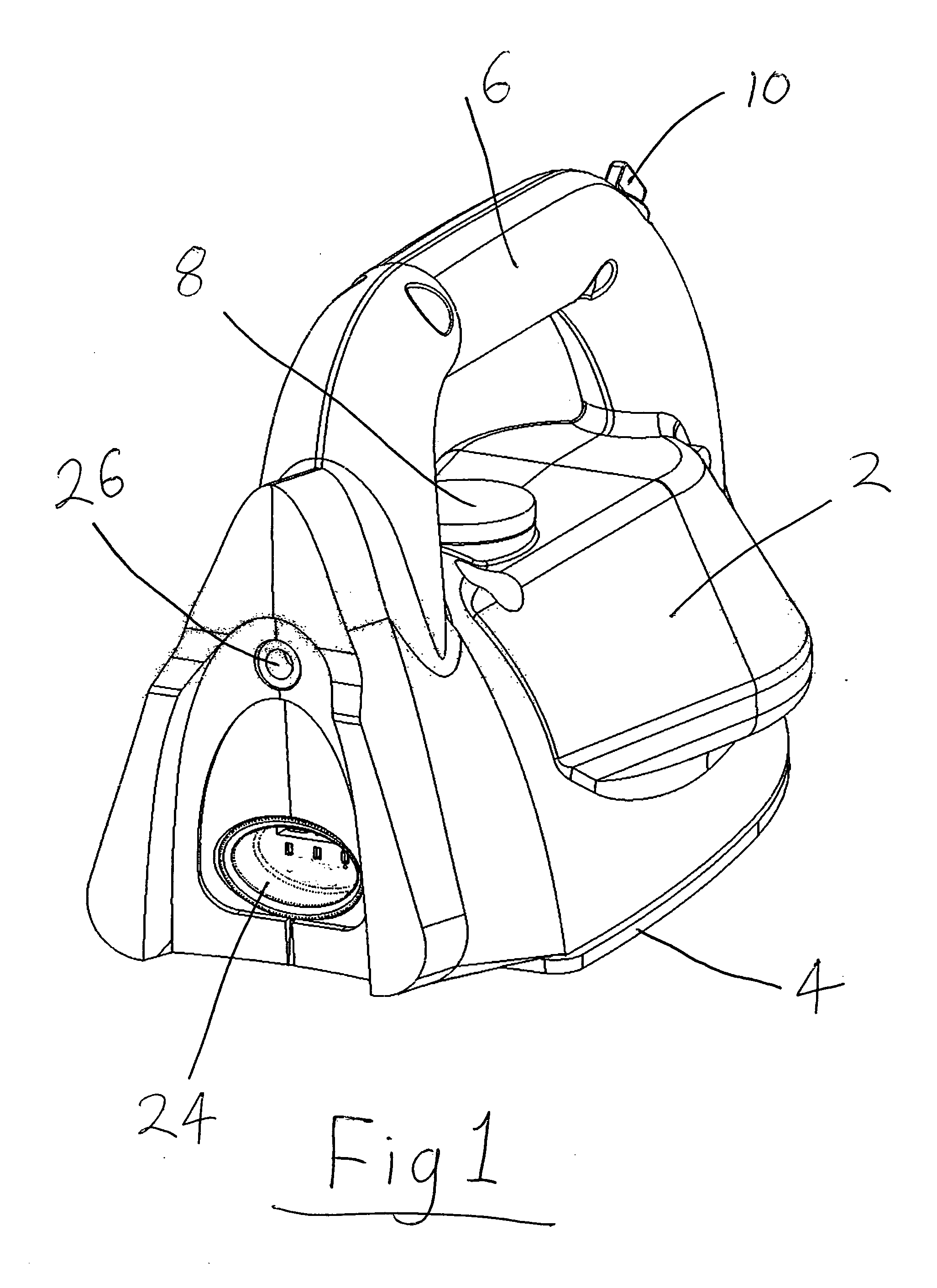
[0068]FIG. 1 is an external view of a steam iron 1 which embodies several aspects of the invention. In FIG. 1 can be seen the main body 2, an electrically heated sole plate 4 and a handle 6. A temperature selector knob 8 is provided on the body 2 beneath the handle 6. A further knob 10 is provided on the front of the handle 6 to allow a user to control the amount of steam supplied by the iron (alternatively it could simply allow steam to be switched on or off). At the rear of the iron is a cordless electrical connector 24—here the male part of the Applicant's P75 cordless electrical connector set but of course any other suitable connector could be used—and a water connector 26.

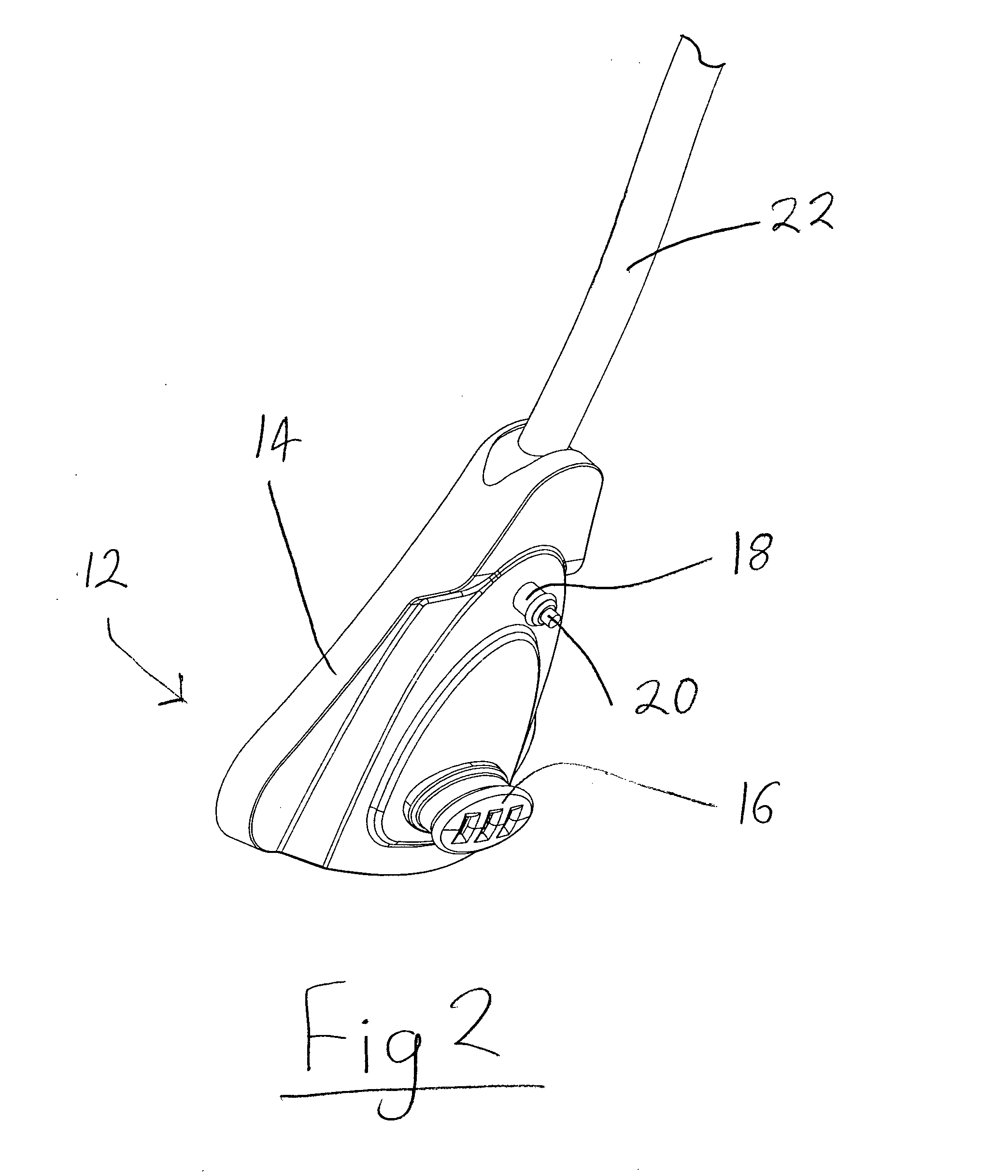
[0069]FIG. 2 shows an adaptor unit 12 for connection to the rear of the iron for supplying the iron with electrical power and water. The adaptor comprises an outer body 14. Projecting from one face of the body 14 is the female part 16 the Applicant's P75 cordless connector set. Above the electrical connector 1...


PUM


Abstract

A steam generating appliance such as an electric iron comprises a base unit and a hand-held mobile unit which can be releasably coupled to the base unit. The base unit comprises a reservoir for water and a pump for pumping water from the reservoir into the mobile unit when the mobile unit is coupled to the base unit. The mobile unit comprises a boiler and an on-board reservoir for water, wherein the on-board reservoir is adapted to store water received from the base unit under pressure and to deliver the water to the boiler under the control of a user-operable valve.

Description

[0001]This application is entitled to the benefit of, and incorporates by reference essential subject matter disclosed in PCT Application No. PCT / GB2010 / 000212 filed on Feb. 4, 2010, which claims priority to Great Britain Application No. 0901855.7 filed Feb. 5, 2009. It is also related to PCT Application No. PCT / GB2010 / 000206 filed on Feb. 4, 2010.BACKGROUND OF THE INVENTION[0002]1. Technical Field[0003]This invention relates to the electric generation of steam for use in domestic irons, steam cleaners, wallpaper strippers and other hand-held steam generating appliances.[0004]2. Background Information[0005]Domestic steam irons have been around for a long time. They comprise a sole plate which is flat and intended to contact the item to be ironed and which is normally heated by means of a sheathed electrical resistance heater mounted to or embedded in the upper side of the sole plate. Traditionally, such irons which are designed to produce steam in order to improve ironing have a sem...

Claims


Application Information

Patent Timeline
Patent Type & Authority Applications(United States)
IPC IPC(8): D06F75/12F22B1/28D06F75/14
CPCD06F75/12D06F79/026D06F75/14D06F75/22D06F79/02
Inventor COLLINSON, MARC GIBSONGIBBS, NICHOLAS EDWARDASHTON, STEVEN ANTHONYGARVEY, VINCENT JOSEPH
Owner STRIX LTD
Why Eureka
Try Eureka