Imaging device having manual and auto focus and a control method for the imaging device

a control method and imaging device technology, applied in the field of digital cameras having a live view display function, can solve the problem of no longer being able to use an af (auto focus) mechanism, and achieve the effect of small time lag and high precision

Inactive Publication Date: 2011-07-12
OLYMPUS CORP
View PDF7 Cites 3 Cited by
  • Summary
  • Abstract
  • Description
  • Claims
  • Application Information

AI Technical Summary

Benefits of technology

[0008]The present invention has as its object to provide an imaging device that can perform focusing with a small time lag and with high precision in the case of imaging from a live view display function, and a control method for an imaging device.

Problems solved by technology

However, in a digital single lens reflex camera, in order to carry out live view display a movable mirror that is arranged in the imaging optical path is temporarily retracted, which means that during live view it is no longer possible to use an AF (Auto Focus) mechanism that employs a conventional phase difference method where an amount of defocus of the photographing leans is detected using subject light flux that has been reflected by a sub-mirror attached to the moveable mirror.

Method used


Image

  • Imaging device having manual and auto focus and a control method for the imaging device
  • Imaging device having manual and auto focus and a control method for the imaging device
  • Imaging device having manual and auto focus and a control method for the imaging device

Examples


Embodiment Construction

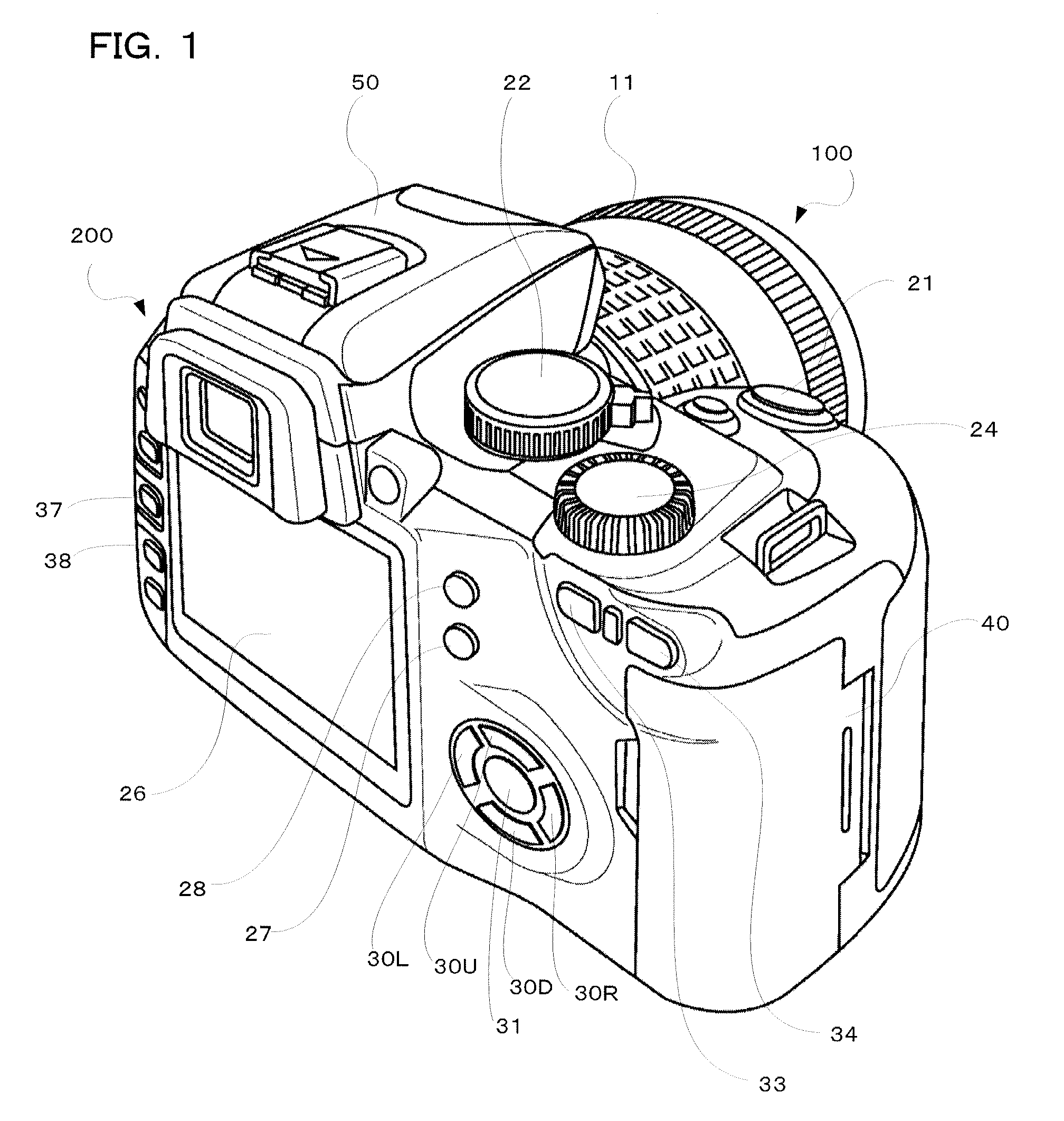
[0024]In the following, one preferred embodiment using a digital single lens reflex camera adopting the present invention will be described using the drawings. FIG. 1 is an external perspective drawing of a digital single lens reflex camera relating to an embodiment of the present invention seen from a rear surface.

[0025]A release button 21, exposure mode dial 22, information setting dial 24 strobe 50 etc. are arranged on the upper surface of the camera body 200. The release button 21 has a first release switch that turns on if the photographer presses the button down halfway, and a second release switch that is turned on when the button is pressed down fully. By turning this first release switch (hereafter called 1R) on, the camera carries out exposure preparation operations such as focal point detection, focusing of the photographing lens, and light measurements for the subject brightness, and by turning the second switch (hereafter called 2R) on, a shooting operation is carried o...


PUM


Abstract

An imaging device, comprising a photographing lens having a manual focus mechanism, an imaging unit for receiving subject light flux, that has been made incident by the photographing lens, on an imaging surface, a display unit for carrying out a live view display operation using image data acquired by the imaging unit, a contrast AF unit for obtaining contrast information of the subject information from image data acquired by the imaging unit and guiding the photographing lens into a specified focus permissible range based on the contrast information, and a control unit for, when a manual focus operation is carried out after executing a focus adjustment operation using the contrast AF unit during the live view display, carrying out control so that there is a transition to a shooting operation without again executing the focus adjustment operation.

Description

[0001]Benefit is claimed, under 35 U.S.C. §119, to the filing date of prior Japanese Patent Application No. 2007-filed on Aug. 22, 2007. This application is expressly incorporated herein by reference. The scope of the present invention is not limited to any requirements of the specific embodiments described in the application.BACKGROUND OF THE INVENTION[0002]1. Field of the Invention[0003]The present invention relates to a digital camera having a live view display function, and in detail relates to an imaging device, having a so-called live view display function (also called an electronic viewfinder function) for displaying an image acquired by an image sensor on a display unit, capable of focusing a photographing lens using an image signal during this live view display, and to a control method for an imaging device.[0004]2. Description of the Related Art[0005]In a conventional digital camera, observation of a subject image is performed using an optical viewfinder. Recently however,...

Claims


Application Information

Patent Timeline
Patent Type & Authority Patents(United States)
IPC IPC(8): G03B13/20H04N5/232
CPCH04N5/23212H04N5/23293H04N23/672H04N23/673H04N23/651H04N23/633H04N23/632
Inventor KUNISHIGE, KEIJIMIYAZAKI, SATOSHI
Owner OLYMPUS CORP
Why Eureka
Try Eureka