
Pressure guiding tube blockage diagnosing device and blockage diagnosing method

A diagnostic device and pressure guiding tube technology, which is applied in the direction of measuring device, measuring fluid pressure, fluid tightness test, etc., can solve problems such as pressure guiding tube blockage, process variable cannot be measured correctly, and complete equipment influence. stagnation effect

Inactive Publication Date: 2014-02-12
YAMATAKE HONEYWELL CO LTD
View PDF10 Cites 4 Cited by
  • Summary
  • Abstract
  • Description
  • Claims
  • Application Information

AI Technical Summary

Problems solved by technology

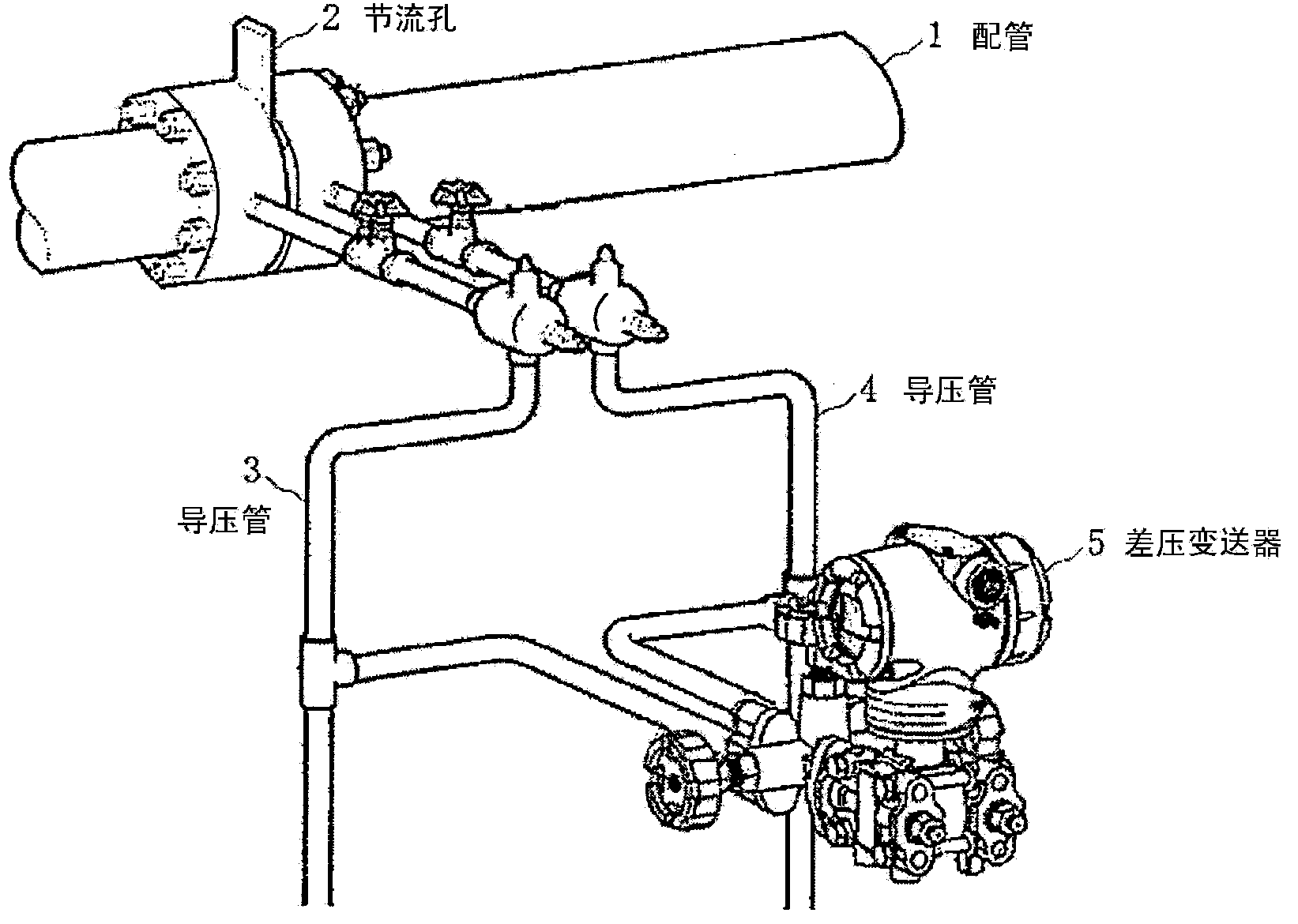
[0003] In such a device structure, solid objects, etc. may adhere to the inside of the pressure guide tube due to the measurement object, and the pressure guide tube may be blocked.
Once the impulse line is completely blocked, the process variable cannot be measured correctly, so it will have a considerable impact on the complete equipment
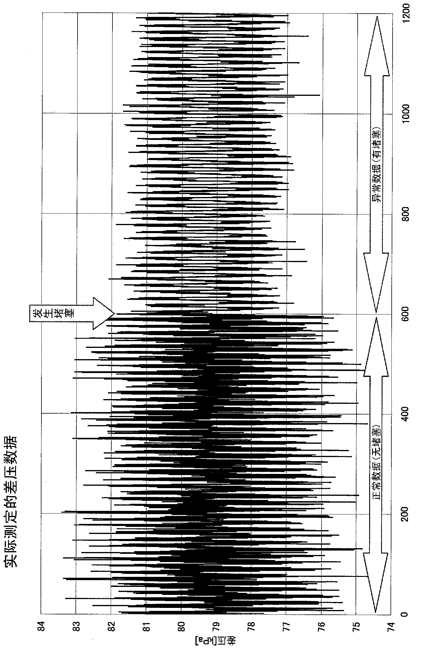
However, since the impulse line transfers pressure to the transmitter before it is completely blocked, the effect of the blockage is difficult to show up in the measured value of the process variable

Method used


Image

  • Pressure guiding tube blockage diagnosing device and blockage diagnosing method
  • Pressure guiding tube blockage diagnosing device and blockage diagnosing method
  • Pressure guiding tube blockage diagnosing device and blockage diagnosing method

Examples


Embodiment approach 1

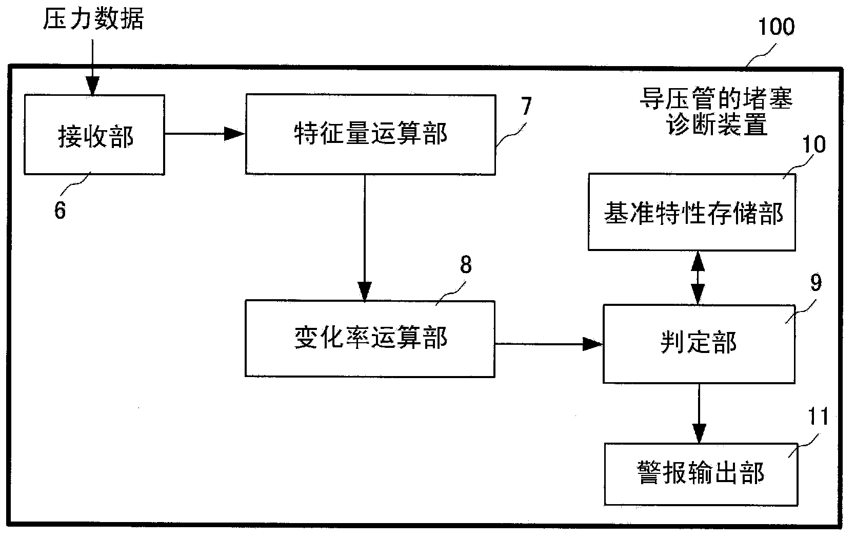
[0051] figure 2 It is a block diagram of a main part of the first embodiment (Embodiment 1) of the pressure guiding tube clogging diagnosis device of the present invention. The clogging diagnosis device 100 for a pressure guide tube includes a receiving unit 6 , a characteristic amount calculating unit 7 , a change rate calculating unit 8 , a determining unit 9 , a reference characteristic storage unit 10 , and an alarm output unit 11 .

[0052] The receiving unit 6 receives differential pressure data from the differential pressure transmitter 5 . The differential pressure data from the differential pressure transmitter 5 corresponds to the pressure data from the pressure detection unit in the present invention. The feature quantity calculating unit 7 divides the time series of differential pressure data received by the receiving unit 6 into a plurality of sections, and obtains a feature quantity indicating the state of pressure fluctuation for each section. In this embodim...

Embodiment approach 2

[0084] In the first embodiment, the rate of change is obtained by the triangular moving average processing as the smoothing processing of the rate of change calculation unit 8 , and in the second embodiment, the rate of change is obtained by the least square method as the smoothing process. In addition, in this Embodiment 2, only the internal processing of the rate-of-change calculation part 8 differs, and its structure is the same as figure 2 The ones shown are the same. For this reason, for embodiment 2 also use figure 2 The structure shown will be described.

[0085] In Embodiment 2, the rate-of-change calculation unit 8 applies the least-squares method to the feature quantities of a fixed time interval up to the interval for each of the intervals to the feature quantities acquired from the feature quantity calculation unit 7 as smoothing. Processing, the slope of the obtained straight line is used as the rate of change of the interval.

[0086] An example of applying ...


PUM


Abstract

A pressure guiding tube blockage diagnosing device includes a receiving portion that receives pressure data from a pressure detecting portion, a feature quantity calculating portion that partitions a time series of pressure data, received by the receiving portion, into a plurality of intervals, and calculates, for each interval, a feature quantity indicating the state of fluctuation of a pressure, a change rate calculating portion that performs, for each interval, a smoothing process on the feature quantities over a specific time interval up to that interval, and calculates, from the feature quantities that have been subjected to the smoothing process, a change rate, for each interval, indicating the change of state of blockage of a pressure guiding tube therein, and an evaluating portion that evaluates the state of blockage of the pressure guiding tube based on the change rate calculated by the change rate calculating portion.

Description

technical field [0001] The present invention relates to a clogging diagnosis device and a clogging diagnosis method of a pressure guiding tube for guiding the pressure of a measurement object fluctuating in pressure to a pressure detecting unit for diagnosing clogging of the pressure guiding tube. Background technique [0002] Conventionally, in the field of the process industry, pressure transmitters and differential pressure transmitters have been used, for example, to detect process variables and control processes. Pressure transmitters are also called pressure transmitters, and differential pressure transmitters are also called differential pressure transmitters. The pressure transmitter is used to measure absolute pressure and gauge pressure, and the differential pressure transmitter is used to measure the differential pressure between two points, and is used for the determination of process variables such as pressure, flow, liquid level, and specific gravity. Generall...

Claims


Application Information

Patent Timeline
Patent Type & Authority Applications(China)
IPC IPC(8): G01L27/00
CPCG01L9/00G01L27/007G01M3/2815G01L13/00G01L19/12
Inventor 佐藤洋平田原铁也田中雅人
Owner YAMATAKE HONEYWELL CO LTD
Learn More