Self-powered rotary shaft vibration active control system and active control method

An active control system and active control technology, applied in the direction of rotation vibration suppression, vibration suppression adjustment, spring/shock absorber, etc., can solve the problems of poor vibration suppression effect, large signal detection error, complicated equipment installation, etc., and achieve measurement error Small, responsive, and time-consuming effects

Active Publication Date: 2020-02-18
XI AN JIAOTONG UNIV
View PDF11 Cites 4 Cited by
  • Summary
  • Abstract
  • Description
  • Claims
  • Application Information

AI Technical Summary

Problems solved by technology

[0006] To address the above problems, the present invention provides a self-powered active shaft vibration control system and active control method. The entire system can choose a more suitable installation method according to actual needs. It is easy to install and disassemble, and can be directly installed on the shaft to play a role. The detection and processing speed of the vibration signal of the rotating shaft is fast, and the suppression effect is good, which can effectively solve the complex installation of equipment in the traditional active vibration control system of the rotating shaft, the need for external power supply, difficult wiring, large signal detection error, long processing time, time lag Large, poor vibration suppression effect, etc., can well realize the active control of the radial vibration of the rotating shaft

Method used


Image

  • Self-powered rotary shaft vibration active control system and active control method
  • Self-powered rotary shaft vibration active control system and active control method

Examples


Embodiment Construction

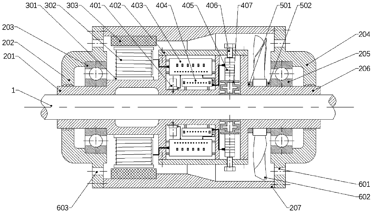
[0047] The following will refer to the attached Figure 1 to Figure 2 Specific examples of the present invention are described in more detail. Although specific embodiments of the invention are shown in the drawings, it should be understood that the invention may be embodied in various forms and is not limited to the embodiments set forth herein. Rather, these embodiments are provided for more thorough understanding of the present invention and to fully convey the scope of the present invention to those skilled in the art.

[0048]It should be noted that certain terms are used in the specification and claims to refer to specific components. Those skilled in the art should understand that they may use different terms to refer to the same component. The specification and claims do not use differences in nouns as a way of distinguishing components, but use differences in functions of components as a criterion for distinguishing. "Includes" or "comprises" mentioned throughout t...


PUM


Abstract

The invention discloses a self-powered rotary shaft vibration active control system and an active control method. In the self-powered rotary shaft vibration active control system, an inner housing isfixedly connected with a rotary shaft; a first end cover can be rotatably connected to the inner housing; a second end cover can be rotatably connected to the inner housing; the outer housing is fixedly connected to the first end cover and the second end cover; a permanent magnet is fixedly connected with the outer housing; a coil rack is fixedly mounted on the inner housing; a magnet exciting coil is wound on the coil rack, and generates relative motion with a permanent magnet to generate electric energy; an accelerated speed sensor is fixedly connected to the rotary shaft to measure a vibration signal of the rotary shaft in real time; an elastic element is fixedly connected to the rotary shaft; an actuator is fixedly connected to the elastic element, so that applied acting force acts onthe rotary shaft through the elastic element; the controller is electrically connected to the magnet exciting coil and the accelerated speed sensor; by responding to the vibration signal, the controller analyzes and processes the vibration signal to form a control signal; and by responding to the control signal, the actuator applies acting force on the rotary shaft through the elastic element to actively control radial vibration of the rotary shaft.

Description

technical field [0001] The invention relates to the technical field of active control, in particular to a self-powered rotating shaft vibration active control system and an active control method. Background technique [0002] With the rapid development of science and technology, the degree of mechanical industrialization is also increasing rapidly, and the mechanical equipment produced by modern industry is gradually becoming more complex, high-speed and automatic. Sophisticated industrial production processes are increasingly dependent on the efficient, reliable, safe and stable operation of motors and related mechanical equipment. Mechanical vibration is harmful to most industrial machinery / engineering structures and instruments. It is often the direct cause of mechanical and structural vicious damage and failure. The vortex causes the bridge body to torsional vibration and vibrate up and down and collapse. In 1972, a 660,000-kilowatt steam turbine generator set at the H...

Claims


Application Information

Patent Timeline
Patent Type & Authority Applications(China)
IPC IPC(8): F16F15/00F16F15/10
CPCF16F15/002F16F15/10
Inventor 刘金鑫张骞乔百杰杨亮东陈雪峰
Owner XI AN JIAOTONG UNIV
Why Eureka
Try Eureka