
Surface Analyzer

Active Publication Date: 2012-03-15
SHIMADZU CORP
View PDF6 Cites 0 Cited by
  • Summary
  • Abstract
  • Description
  • Claims
  • Application Information

AI Technical Summary

Benefits of technology

[0028]As described thus far, with the surface analyzer according to the present invention, users can quickly and easily grasp various kinds of positional relationships, such as the positional relationship between one or more distribution images of a certain physical quantity obtained for small ranges and the entire range that can be observed or measured, the positional relationship among a plurality of distribution images, or the location of a portion which is within the range that can be observed or measured and which has not yet been subjected to a magnified observation or measurement. Therefore, users can efficiently perform necessary operations for the observation or measurement of a sample surface. The number of operational errors resulting from visual comparison of a plurality of images or other reasons will also be reduced.

Problems solved by technology

Even when a broad-area image showing the altitude and a magnified observation image showing a certain physical quantity different from the altitude are simultaneously shown on the same display screen, it is difficult to know which portion on the broad-area image corresponds to the magnified observation image selected or specified by the observer.
Therefore, when the user wants to observe the distribution of a certain physical quantity on a desired portion of the sample while grasping the positional relationship of a plurality of magnified observation images which were previously taken for a certain physical quantity, the task will be very time-consuming and inefficient.

Method used


Image

  • Surface Analyzer
  • Surface Analyzer
  • Surface Analyzer

Examples


Embodiment Construction

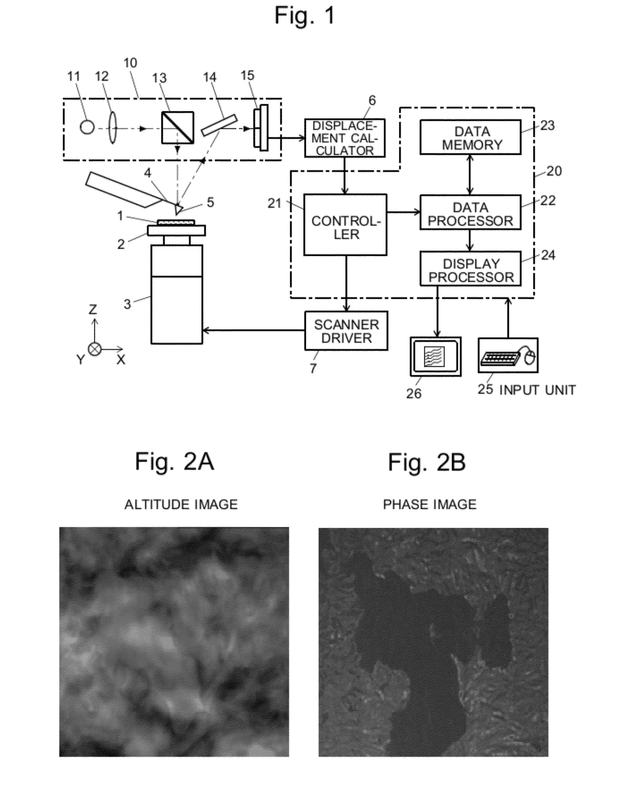
[0037]A scanning probe microscope (SPM) as one embodiment of the surface analyzer according to the present invention is hereinafter described with reference to the attached drawings. FIG. 1 is a configuration diagram showing the main components of the SPM in accordance with the present embodiment.

[0038]A sample 1 to be observed is placed on a sample stage 2 mounted on the upper end of a substantially cylindrical scanner 3. The scanner 3 has a plurality of piezoelectric elements and is capable of moving the sample 1 in the X and Y directions as well as finely adjusting its position in the Z direction in accordance with voltages applied from a scanner driver 7. A cantilever 4 having a probe at its tip is located above the sample 1. The cantilever 4 is driven to oscillate by an exciter including a piezoelectric element (not shown). Located above the cantilever 4 is a displacement detection unit 10 for detecting the displacement of the cantilever 4 in the Z direction. The displacement d...


PUM


Abstract

A technique for allowing users to efficiently specify a region of interest (ROD on a sample for a certain physical quantity (e.g. phase) other than the altitude is provided. A range-indicating image 34 showing a range that can be observed on a sample is displayed on a navigation window 33 in a sample observation display screen 30. An ROI-indicating frame 35 for specifying a magnified observation range is superposed on the range-indicating image 34. A list of thumbnails of previously taken magnified images for the same sample is displayed on an image history display window 32. When an observer selects any image from this list, the thumbnail of the selected image is mapped onto the range-indicating image 34. With reference to this image, the observer can change the position, size and / or angle of the ROI-indicating frame 35 by a mouse operation. In response to this operation, a magnified image of the sample within the new ROI is acquired.

Description

TECHNICAL FIELD[0001]The present invention relates to a surface analyzer capable of acquiring two-dimensional distribution data of different kinds of physical quantities on a predetermined area of a sample. Typical examples of such surface analyzers include scanning probe microscopes, laser microscopes and electron probe micro analyzers.BACKGROUND ART[0002]An observation of a sample surface using a microscope normally includes a first step of taking a low-magnification image (broad-area image) with a large visual field on a sample, displaying the broad-area image on a display screen to allow an observer to search for a desired portion on the sample, and a second step of performing a magnified observation to acquire a magnified image with a smaller visual field including the desired portion, displaying the magnified image. To improve the efficiency of such operations, various techniques have been developed and proposed.[0003]For example, Patent Document 1 discloses a technique in whi...

Claims


Application Information

Patent Timeline
IPC IPC(8): G09G5/377
CPCG01Q30/04B82Y35/00
Inventor MORIMOTO, TAKASHI
Owner SHIMADZU CORP
Learn More