Composite delivery system

a delivery system and composite technology, applied in the field of syringe systems, can solve the problems of greatest progressive shortening of the overall length of the syringe system, and achieve the effects of reducing the overall length of the delivery system, and reducing the overall length of the devi

Inactive Publication Date: 2012-03-15
ULTRADENT PROD INC
View PDF34 Cites 13 Cited by
  • Summary
  • Abstract
  • Description
  • Claims
  • Application Information

AI Technical Summary

Benefits of technology

[0008]As a result of this configuration, as the viscous material is progressively dispensed (i.e., by rotating the syringe barrel relative to the sheath), the overall length of the delivery system is progressively reduced as viscous material is dispensed. Thus, the length of the delivery system is greatest when new, before any viscous material has been dispensed and the plunger stem has not been advanced to any significant degree within the syringe barrel. The length of the delivery system is shortest when all of the viscous material within the hollow interior chamber that can be dispensed has been dispensed, and the plunger stem has been fully advanced into the syringe barrel as far as it is able. Shortening of the device length occurs as a result of the syringe barrel being progressively advanced into the sheath as the plunger stem simultaneously advances into the syringe barrel. In other words, more of the syringe barrel is progressively enclosed within the interior chamber of the sheath as more viscous material is dispensed, and the increase in overlap between the syringe barrel and sheath results in progressive shortening of the overall length of the syringe system.

Problems solved by technology

Thus, the length of the delivery system is greatest when new, before any viscous material has been dispensed and the plunger stem has not been advanced to any significant degree within the syringe barrel.
In other words, more of the syringe barrel is progressively enclosed within the interior chamber of the sheath as more viscous material is dispensed, and the increase in overlap between the syringe barrel and sheath results in progressive shortening of the overall length of the syringe system.

Method used


Image

  • Composite delivery system
  • Composite delivery system
  • Composite delivery system

Examples


Embodiment Construction

I. Introduction

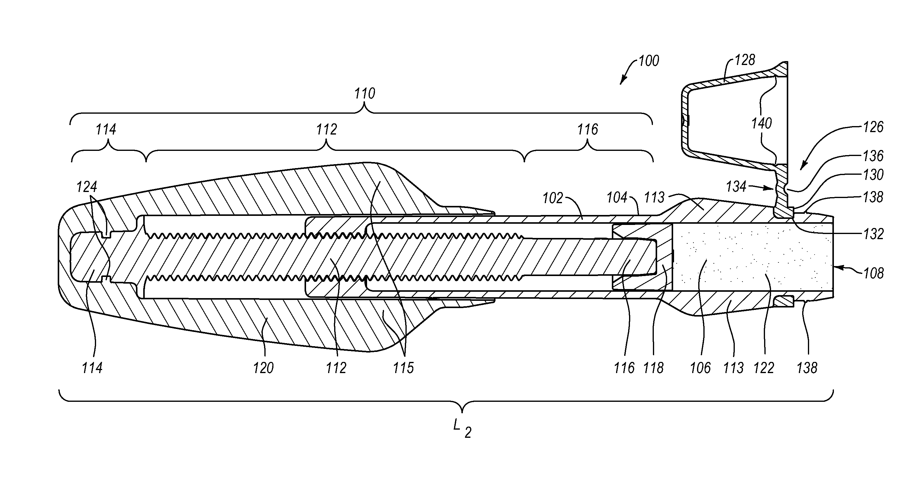
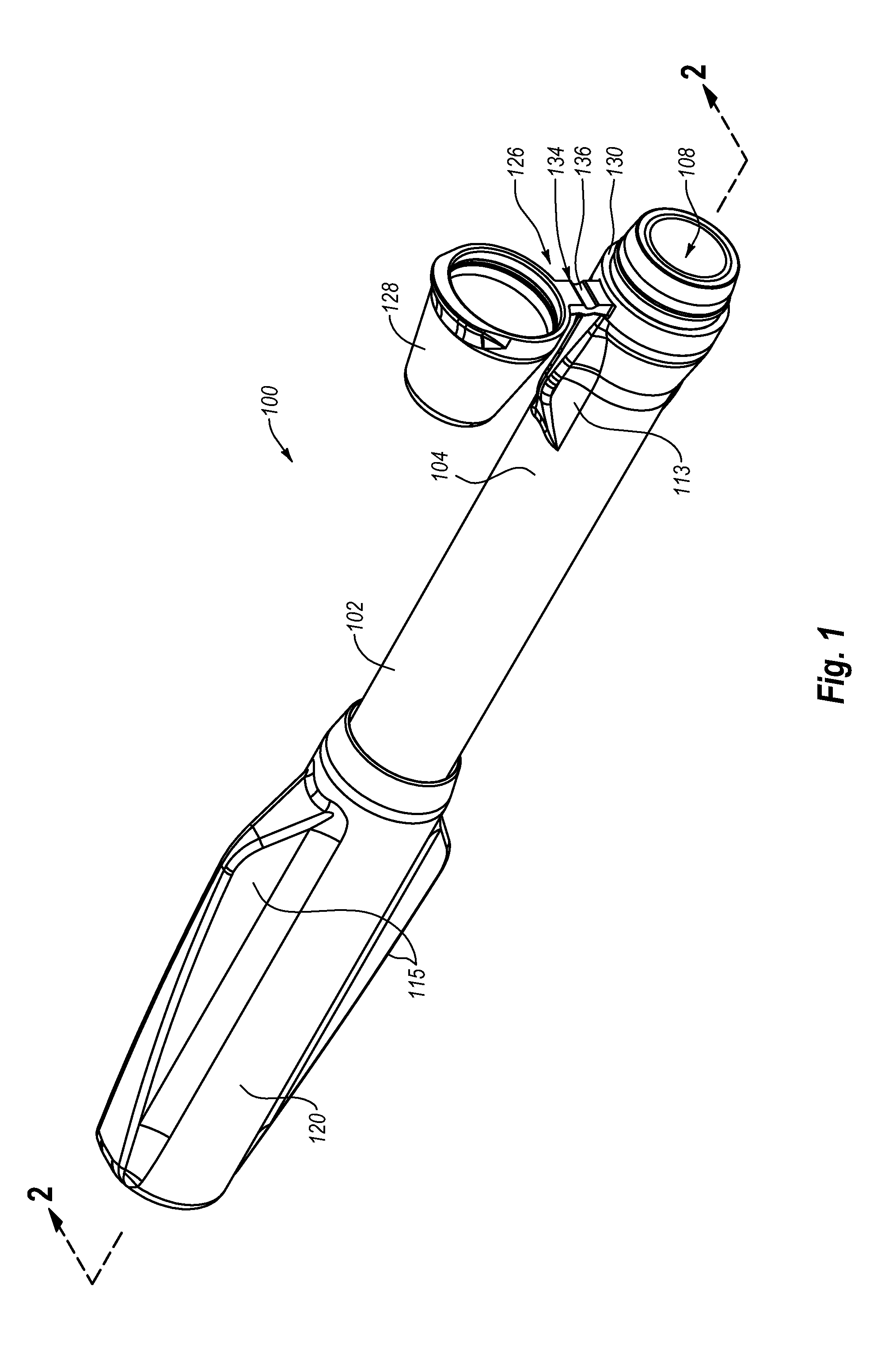
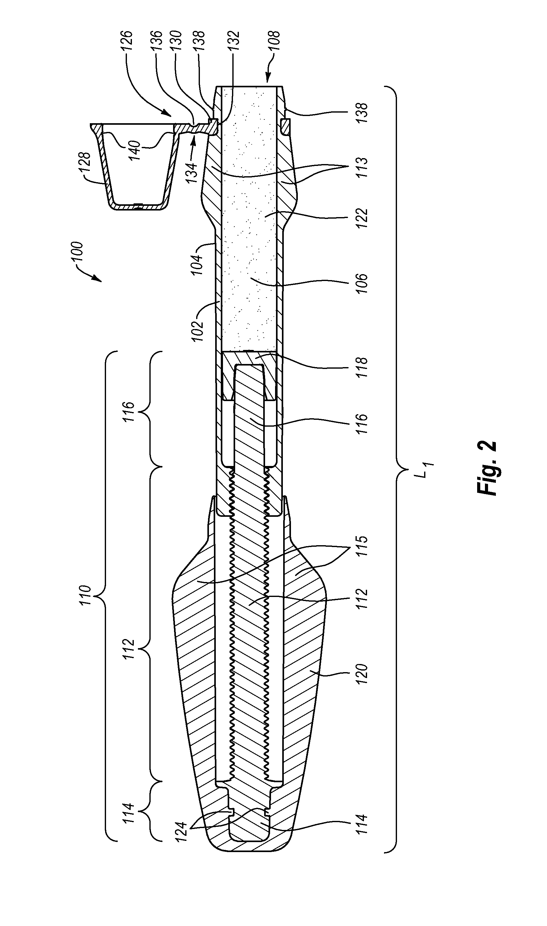
[0016]The invention generally relates to a syringe delivery system for dispensing a viscous material through a syringe delivery opening. The syringe delivery system includes a syringe barrel, a plunger stem, and a sheath. The syringe barrel includes an exterior gripping surface and a hollow interior chamber for holding a viscous material to be dispensed, as well as a delivery opening at the distal delivery end of the barrel through which the viscous material is dispensed. The plunger stem includes a threaded shaft that threadably engages corresponding threads at the proximal end of the syringe barrel so that the plunger stem is at least partially disposed within the hollow interior chamber of the syringe barrel. The plunger stem is selectively longitudinally advanceable within the syringe barrel so as to dispense the viscous material from the interior chamber through the delivery opening. The sheath covers at least the proximal end of the threaded shaft of the plunge...


PUM


Abstract

A syringe delivery system for dispensing a highly viscous material through a syringe delivery opening includes a syringe barrel having a delivery opening, a plunger stem including a threaded shaft that threadably engages a proximal end of the syringe barrel for selectively dispensing a viscous material through the delivery opening, and a sheath. The sheath is rigidly attached with the plunger stem so that the plunger stem and sheath rotate together in unison relative to the syringe barrel. The sheath and syringe barrel may enclose the plunger stem. In order to dispense a viscous material, the syringe barrel is rotated relative to the sheath, causing the syringe barrel to be progressively received within the sheath and simultaneously forcing the plunger stem further into the syringe barrel so as to dispense a viscous material from the delivery opening.

Description

CROSS-REFERENCE TO RELATED APPLICATIONS[0001]The present application claims the benefit of U.S. Provisional Patent Application Ser. No. 61 / 382,079 filed Sep. 13, 2010 and entitled COMPOSITE DELIVERY SYSTEM, herein incorporated by reference in its entirety.BACKGROUND[0002]1. The Field of the Invention[0003]The present invention relates to syringe systems that are used for storing and dispensing materials therefrom. More particularly, the present invention relates to a dental syringe system that provides for controllable doses of a highly viscous, pliable, curable (e.g., light-activated) dental composite.[0004]2. The Relevant Technology[0005]Cosmetic and / or functional augmentations of a tooth due to chipping or decay are common dental procedures. Typically, the dentist will apply a resin-based, light-activated dental composite to the tooth in order to fill a chipped or missing area. When the dental composite closely matches the natural color of the tooth, the repair job is barely, if ...

Claims


Application Information

Patent Timeline
Patent Type & Authority Applications(United States)
IPC IPC(8): A61C5/04
CPCB65D83/0011A61C5/062A61C5/62
Inventor CANNON, WADEMCLEAN, BRUCE S.FISCHER, DAN E.
Owner ULTRADENT PROD INC
Why Eureka
Try Eureka