Apparatus for and method of fitting a stent-graft or similar device

a technology of stent-graft and proximal end, which is applied in the field of stent-graft or similar device apparatus, can solve the problems of affecting the operation, affecting the operation, and affecting the operation, so as to achieve precise adjustment of the proximal end of the device, reduce the length of the device, and increase the separation

Active Publication Date: 2009-08-13
COOK MEDICAL TECH LLC
View PDF4 Cites 10 Cited by
  • Summary
  • Abstract
  • Description
  • Claims
  • Application Information

AI Technical Summary

Benefits of technology

[0014]Adjustment of the tie elements in a direction which reduces the spacing between them can in practice provide for a reduction in the length of the device held by the tie elements and as a result can cause the device to curve in the direction of the tie elements, by pulling on one side at the proximal end of the device. Adjustment of the tie elements in a direction to increase the separation therebetween can push the proximal end of the device in an upstream direction.
[0015]Similarly, the carrier can be moved such that both tie elements are pushed or pulled together, thereby allowing for precise adjustment of the proximal end of the device in a patient. This is particularly useful in the placement of the device where there is little room for error.

Problems solved by technology

Even though such a procedure is possible into the aortic arch, it is mired in difficulties as a result of the tight curvature of the latter.
One such difficulty arises in connection with the proximal end of the stent-graft, which is liable to be incorrectly fitted such that it incompletely seals around the inner wall of the aorta as a result of the curvature imparted to the stent-graft.
This can lead to leakage of blood around the outside of the stent-graft and thus of a less than effective treatment.
Furthermore, as a result of the non-optimal placement of the stent-graft using known procedures, there is a limit to the length of neck of healthy vascular wall which is needed to provide a seal around the proximal end of the stent-graft.
This limits the application of such stent-grafts, in particular for the treatment of aneurysms close to a branch vessel.
In addition, in some instances at least, a part of the proximal end of the stent-graft can remain loosely located in the vessel, leading to premature fatigue failure and thrombus effects.
However, if the device is either fitted too far downstream or pulled too much during fitting, the procedure needs to be repeated, for example by withdrawing the device back into its delivery introducer and starting the deployment operation afresh.
Repeating the procedure increases operating time, trauma to the patient and still does not guarantee a successful outcome.

Method used


Image

  • Apparatus for and method of fitting a stent-graft or similar device
  • Apparatus for and method of fitting a stent-graft or similar device
  • Apparatus for and method of fitting a stent-graft or similar device

Examples


Embodiment Construction

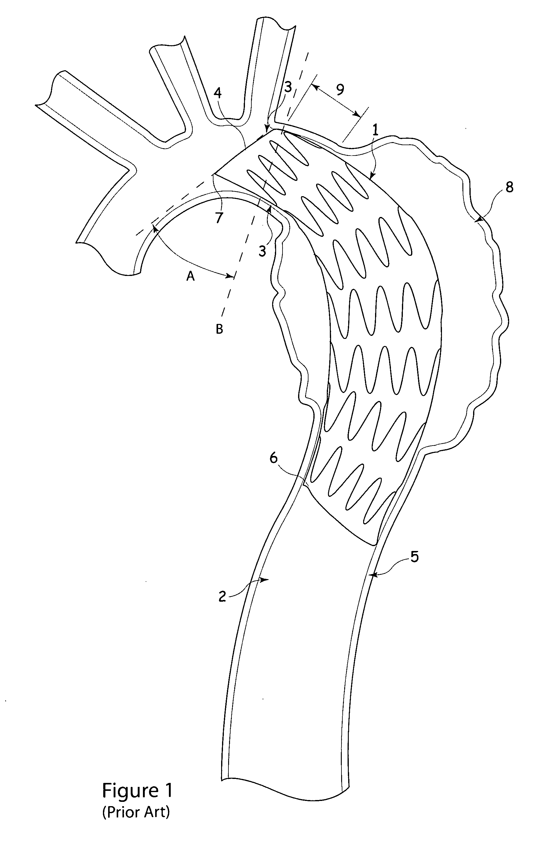
[0030]For the purposes of this disclosure, when used in connection with description of a stent-graft or other implantable device, the term “proximal” refers to a part or position closest to the heart, that is upstream in the direction of blood flow, while the term “distal” refers to a part or position furthest from the heart. On the other hand, when used in connection with an introducer assembly the term “proximal” refers to a position or part closest to the surgeon and typically kept outside the patient, while the term “distal” refers to a position or part furthest from the surgeon and in practice furthest into a patient during a deployment procedure.

[0031]Referring to FIG. 1, there is shown an example of deployment of a stent-graft 1 within the aorta 2 of a patient for the treatment of, for example, an aneurysm 8. In this particular example, the stent-graft extends part-way into the aortic arch 3 at its proximal end 4, down to the thoracic aorta 5 at its distal end 6. The curvatur...


PUM


Abstract

A fitting device (104) for fitting a stent-graft (100) into a lumen of a patient includes a catheter (110), a cannula (112) reciprocably carried in the catheter (110) and a pair of gripper claws (106) in the cannula (112). The gripper claws (106) grip onto a stent (102) at the proximal end (128) of the stent-graft (100) which a suture loop (108) is tied to a stent (102) at an intermediate position along the stent graft (100). The stent-graft (100) can be curved by pulling the end-most stent (102) backwards, that is by retracting the cannula (112) into the catheter (110) while the gripper claws (106) grip onto the stent (102). The proximal end of the stent-graft (100) can also be adjusted position-wise by moving the cannula (112) into and out of the catheter (110). Thus, precise positioning and curving of the stent-graft (100) can be achieved.

Description

CROSS-REFERENCE TO RELATED APPLICATIONS[0001]This application claims priority of provisional application Ser. No. 61 / 065,536, filed Feb. 13, 2008 and provisional application Ser. No. 61 / 069,115, filed Mar. 12, 2008.TECHNICAL FIELD[0002]The present invention relates to apparatus for and a method of fitting a stent-graft, stent or other device into a lumen of a patient, particularly into a highly curved lumen such as the aortic arch and into locations which provide little room for error in the placement of the device, such as lumens having short necks of healthy vascular wall.BACKGROUND ART[0003]Prostheses for the repair of vascular defects, including for example vascular aneurysms, are well known in the art. A common prosthesis for treatment of such a medical condition is a stent-graft.[0004]Prostheses of this type are typically deployed endoluminally through a vein or artery adjacent a surface of a patient. For example, aortic prostheses are commonly fed through the femoral artery. ...

Claims


Application Information

Patent Timeline
Patent Type & Authority Applications(United States)
IPC IPC(8): A61F2/06
CPCA61B2017/22035A61B2017/2215A61F2/95A61F2002/9534A61F2002/9505A61F2002/9511A61F2002/075
Inventor JENSEN, KIM MOEGELVANGOHLENSCHLAEGER, BENT
Owner COOK MEDICAL TECH LLC
Why Eureka
Try Eureka