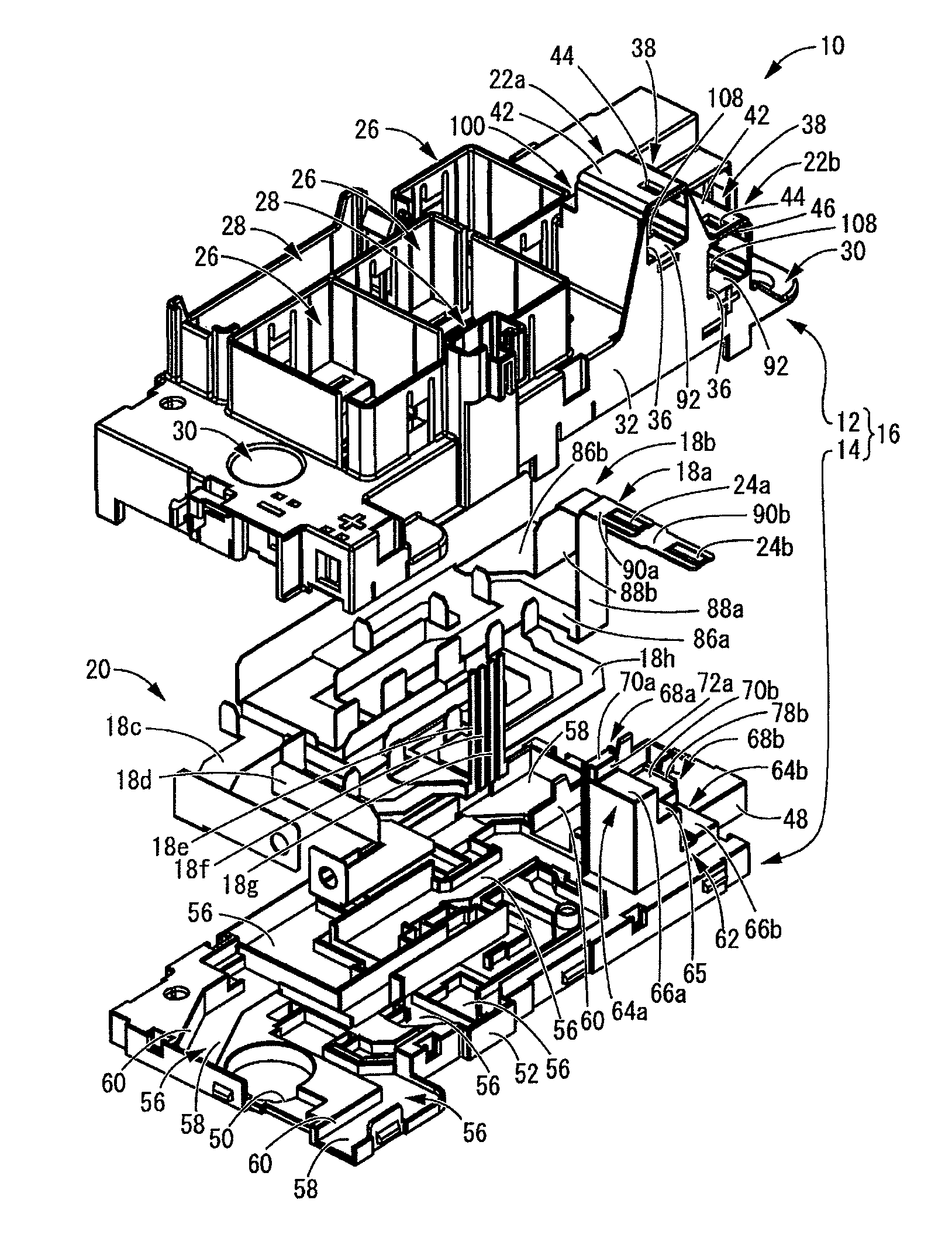
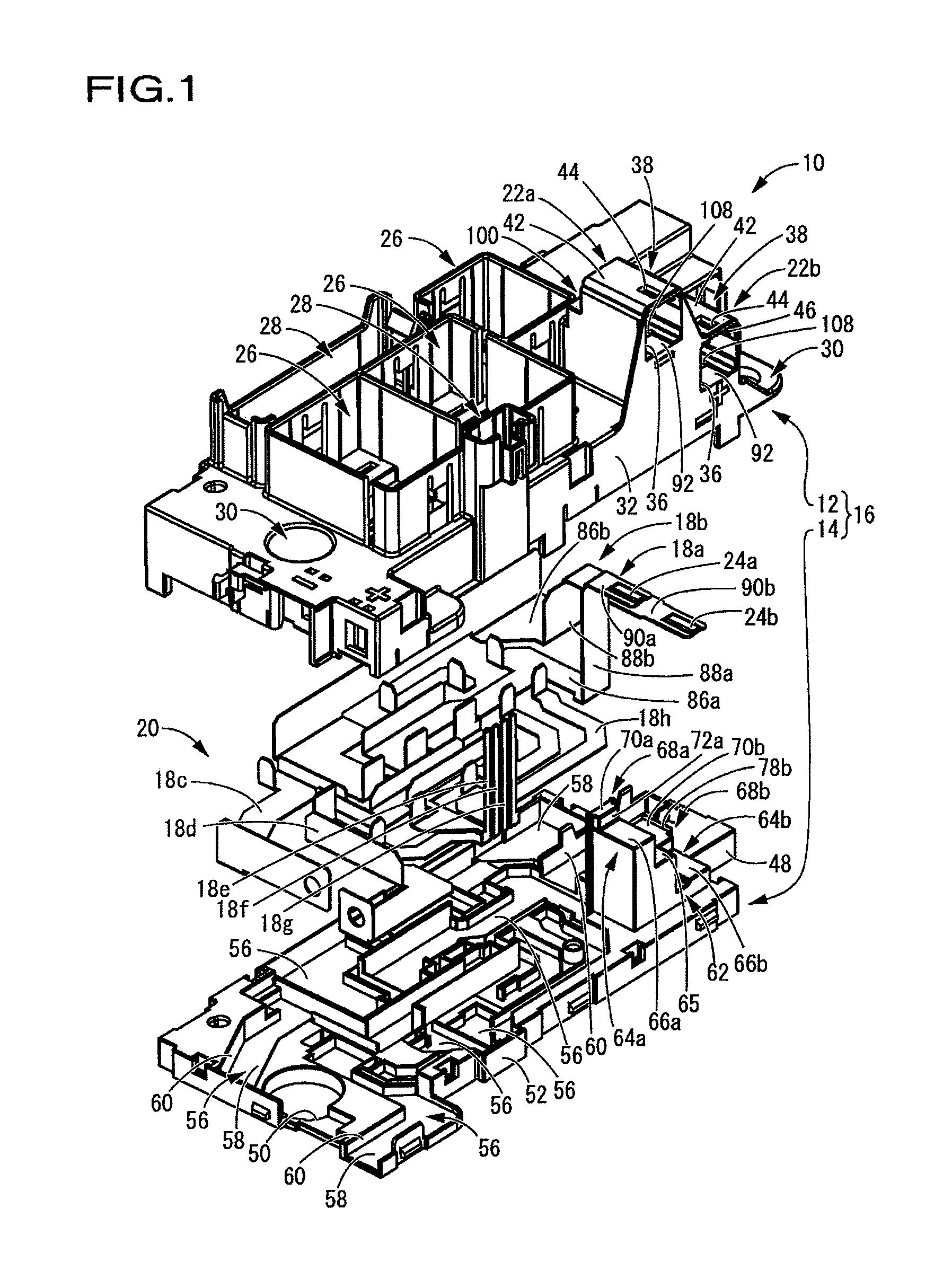
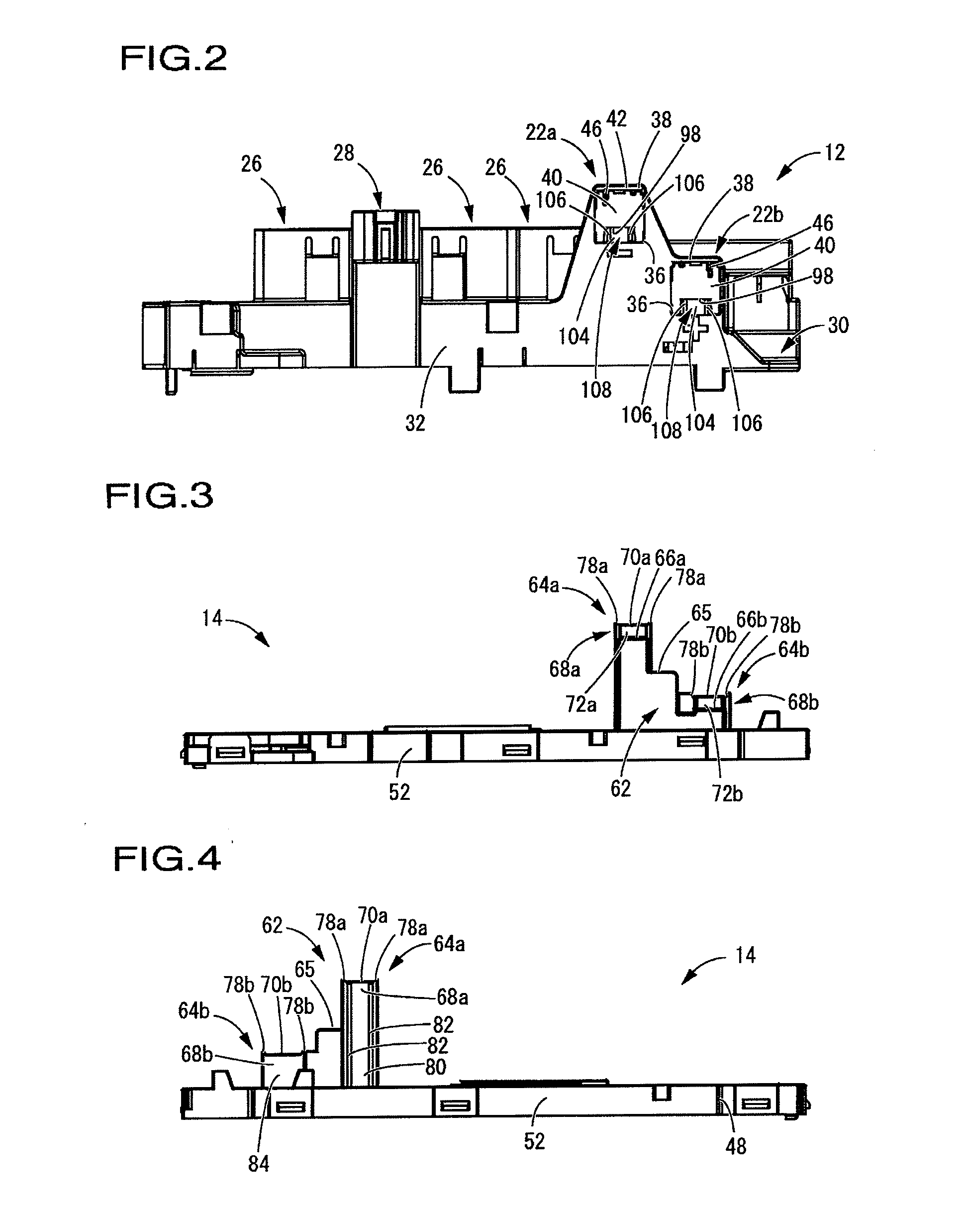
Electric junction box

a junction box and junction box technology, applied in the field of electric junction boxes, can solve the problems of increasing the number of components, difficulty in mounting, and deformation of the connection housing, and achieve the effects of enhancing shape stability, connection stability, and reducing the decline in the shape stability of the connection

Active Publication Date: 2012-03-15
SUMITOMO WIRING SYST LTD +1
View PDF2 Cites 24 Cited by
  • Summary
  • Abstract
  • Description
  • Claims
  • Application Information

AI Technical Summary

Benefits of technology

[0022]According to the fifth aspect of the present invention, the window in the connection housing is provided distant from the corner of the tubular portion. Thus, the reinforcement effect of the corner of the tubular portion can minimize a decline in shape stability of the connection housing due to forming of the open window.
[0023]According to the present invention, the connection housing open to the side is integrally provide...

Problems solved by technology

With an external force or vibration exerted, the cases may thus be displaced from each other, and the connection housing may deform.
Such a deformation of the connection housing causes a displacement between the connection housing and a connection terminal projecting inside, thus possibly causing an electric component to hook as being mounted or causing difficulty in mounting.
In addition, such a deformation of the connection housing causes instability of an electric component mounted inside the housing, thus leading to wear and damage of the electric component and the electric junction box as well as possibly causing a serious defect, such as a connection failure.
In th...

Method used


Image

  • Electric junction box
  • Electric junction box
  • Electric junction box

Examples


first embodiment

[0084]A perpendicular portion support projection 130 is provided in the present embodiment, the perpendicular portion support projection 130 having a wider area than the perpendicular portion support rib 106 in the first embodiment and projecting toward a perpendicular portion 88a of the bus bar 18a (detailed illustration of the entire portion omitted). As shown in FIG. 13, the perpendicular portion 88a of the bus bar 18a is thus held in a sufficient area in the horizontal direction (left-right direction in FIG. 13) between a back surface 80 of the support base 64a on the lower case 14 side and the perpendicular portion support projection 130 on the upper case 12 side. Accordingly, the strength to support the bus bar 18a in the horizontal direction is enhanced.

[0085]As shown in FIGS. 12 and 14, the connection housing 114 of the present embodiment is provided with a plurality of press-fit ribs 132 extending from a back side (bottom side) of the housing portion 100 of the connection h...

second embodiment

[0097]In the second embodiment, the specific shape, position, and number of the positioning projection 118 on each of the support bases 64a and 64b and of the fitting recess 128 in the connection housing 114 are not particularly limited, provided the support bases 64a and 64b and the connection housing 114 can be fitted to each other. For instance, the positioning projection 118 may be provided on the connection housing 114 and the fitting recess 128 may be provided in each of the support bases 64a and 64b. Alternatively, the positioning projection 118 may be provided on each of the support bases 64a and 64b and the connection housing 114, and the fitting recess 128 may be provided in each of the support bases 64a and 64b and the connection housing 114.

[0098]Furthermore, the specific shape, position, and number of the press-fit ribs 132 are not particularly limited, either. For example, of the connection housing 114 and the support bases 64a, 64b, 64c, and 64d that interpose the bus...


PUM


Abstract

A first case is integrally provided with a connection housing open to a side of the first case. A second case is integrally provided with a support base projecting toward the first case and facing inside the connection housing from a window provided in the connection housing. A bus bar included in a connection terminal disposed inside the connection housing is provided along the support base and is interposed between the support base and the first case, and is positioned in a projecting direction of the connection terminal.

Description

CROSS-REFERENCE TO RELATED APPLICATIONS[0001]The present application claims priority under 35 U.S.C. §119 of Japanese Applications No. 2010-207080, filed on Sep. 15, 2010, and No. 2011-064209, filed on Mar. 23, 2011, which are herein expressly incorporated by reference in their entireties.BACKGROUND OF THE INVENTION[0002]1. Field of the Invention[0003]The present invention relates to an electric junction box mounted in a vehicle and the like, particularly to an electric junction box provided with a connection housing, such as a connector housing, open to a side of the electric junction box.[0004]2. Description of Related Art[0005]For efficient electric wirings and improvement in maintenance, electric junction boxes, such as junction boxes and relay boxes, have conventionally been used in electric systems of vehicles and the like. In general, such an electric junction box has a structure in which conductive members, such as a bus bar, that form an internal circuit are provided in an ...

Claims


Application Information

Patent Timeline
IPC IPC(8): H01R12/00
CPCH01R9/226H05K5/0026
Inventor KAWAGUCHI, KIYOFUMIAOKI, OSAMUTAGA, SHUNJI
Owner SUMITOMO WIRING SYST LTD
Why Eureka
Try Eureka