Electromagnetism-assisted forming device and method for dissimilar metal composite boards

A composite plate and dissimilar metal technology, applied in the field of composite plate forming devices, can solve the problems of low forming limit, plate thinning, cracking, etc., and achieve the effects of increasing forming limit, increasing tangential compressive stress, and improving formability

Inactive Publication Date: 2013-07-10
HARBIN INST OF TECH
View PDF8 Cites 23 Cited by
  • Summary
  • Abstract
  • Description
  • Claims
  • Application Information

AI Technical Summary

Problems solved by technology

[0005] The purpose of the present invention is to solve the problem that the forming limit is low in the deep drawing forming process of the existing metal composite sheet, which leads to the serious thinning of the sheet until it breaks during the forming process, and to provide an electromagnetic-assisted forming device for dissimilar metal composite sheets and its method

Method used


Image

  • Electromagnetism-assisted forming device and method for dissimilar metal composite boards
  • Electromagnetism-assisted forming device and method for dissimilar metal composite boards
  • Electromagnetism-assisted forming device and method for dissimilar metal composite boards

Examples


specific Embodiment approach 1

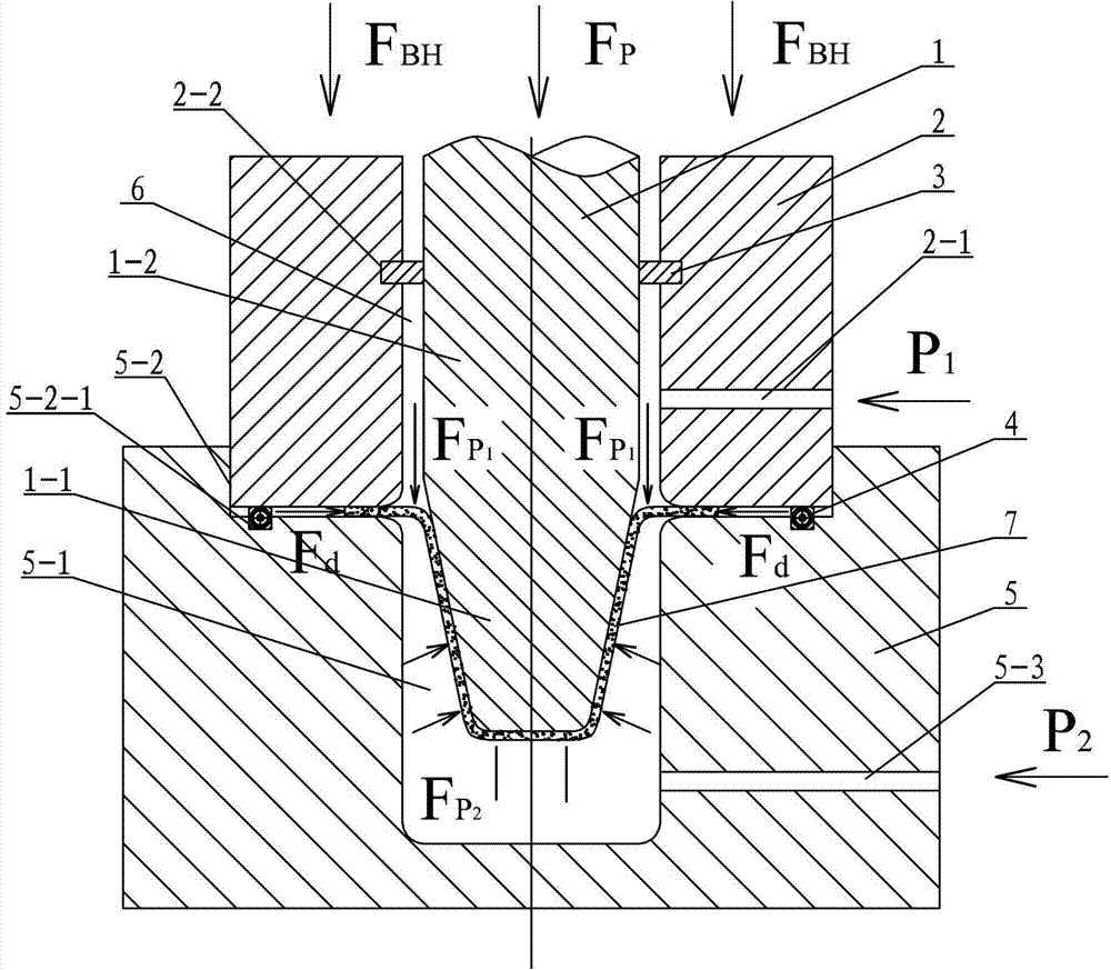
[0018] Specific implementation mode one: combine figure 1 Describe this embodiment, this embodiment comprises punch 1, blank holder ring 2, sealing ring 3, coil 4 and die 5, and the upper end surface of described die 5 is provided with die cavity 5-1 and The binder ring groove 5-2, the bottom surface of the binder ring groove 5-2 is provided with an annular coil groove 5-2-1, the coil 4 is arranged in the annular coil groove 5-2-1, the inner side wall of the binder ring 2 There is an annular sealing ring groove 2-2, the punch of the punch 1 is a round table 1-1, the tail of the punch 1 is a cylinder 1-2, the blank holder 2 is set on the cylinder 1-2, and the blank holder There is a liquid channel 6 between the inner wall of 2 and the cylinder 1-2, the sealing ring 3 is set on the cylinder 1-2 and arranged in the annular sealing ring groove 3-1, and the side wall of the blank holder 2 is provided with an upward The liquid passage 2-1, the side wall of the die 5 is provided wi...

specific Embodiment approach 2

[0019] Specific implementation mode two: combination figure 1 To illustrate this embodiment, the upper liquid inlet channel 2-1 and the lower liquid channel 6-1 of this embodiment are arranged facing each other up and down. Other connection relationships are the same as those in the first embodiment.

specific Embodiment approach 3

[0020] Specific implementation mode three: combination figure 1 Describe this implementation mode, this implementation mode is realized through the following steps:

[0021] Step 1. Place the composite sheet 7 on the bottom surface of the blankholder groove 5-2, and move the blankholder 2 down to a place where the lower end surface of the blankholder 2 is 0.5mm to 2mm away from the upper end surface of the composite sheet 7. Blankholder 2 applies blankholder force F BH 5kN~200kN;

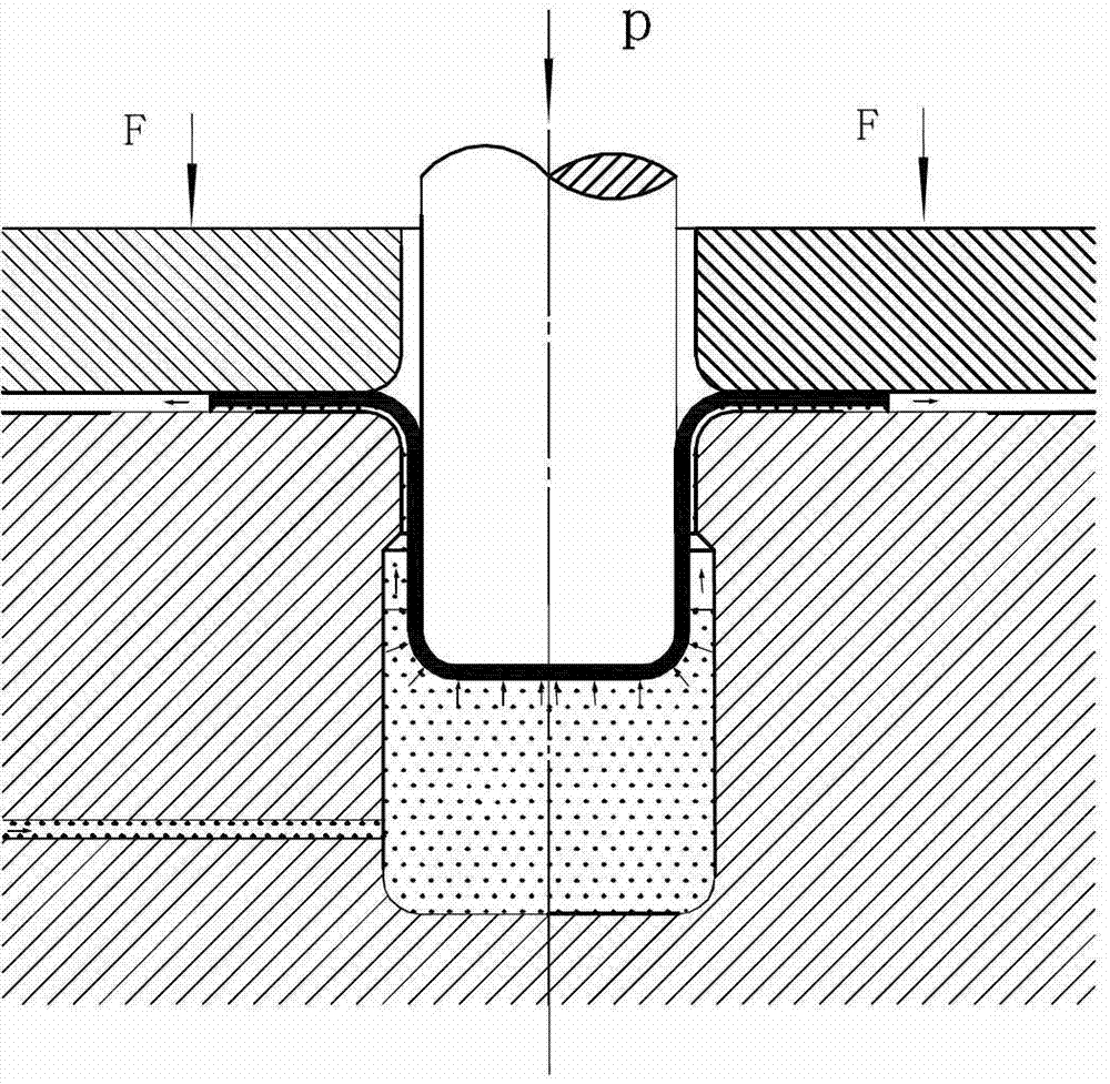
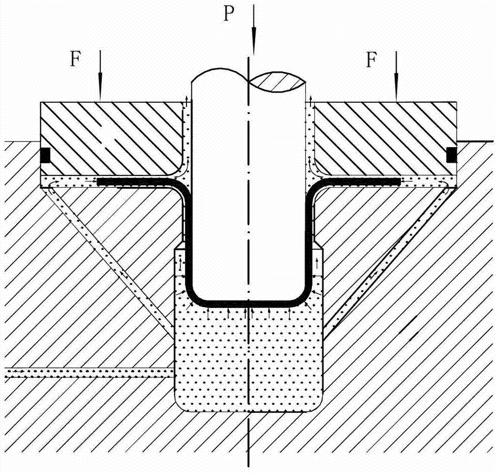
[0022] Step 2. The punch 1 moves down to the upper surface of the composite sheet 7, and at the same time, the positive liquid is applied to the liquid channel 6 from the upper liquid channel 2-1, and its positive liquid pressure P 1 2MPa~50MPa, the reverse liquid is applied from the lower liquid inlet channel 5-3 to the die cavity 5-1, and its reverse liquid pressure P 2 Should be greater than 1.5 times the positive liquid pressure P 1 , less than 100MPa (that is, 100MPa≥P 2 ≥P 1 ), then the...


PUM

PropertyMeasurementUnit
thicknessaaaaaaaaaa
thicknessaaaaaaaaaa
thicknessaaaaaaaaaa

Abstract

The invention relates to an electromagnetism-assisted forming device and method for dissimilar metal composite boards and aims to solve the problem that existing metal composite boards are severely lapped and even broken in a drawing process. According to the forming device, a coil is arranged in an annular coil groove, a liquid channel is disposed between the inner wall of a blank holder and a cylinder, an upper liquid inlet channel is transversely arranged on the side wall of the blank holder, and a lower liquid inlet channel is transversely arranged on the side wall of a female die. The method includes placing the composite boards on the bottom surface of the blank holder; filling forward liquids into the liquid channel, filling reverse liquids into the female die, and exerting radial electromagnetic force Fd on the periphery of a flange of the composite board through the coil; forming the composite board under the combined action of a reverse pressure Fp2, a forward pressure Fp1 and the radial electromagnetic force Fd; and unloading a forward liquid pressure P1 and then a reverse liquid pressure P2, returning a male die and taking the formed part.

Description

technical field [0001] The invention relates to a device and method for forming a composite plate, in particular to a forming method for improving the forming limit of a heterogeneous metal composite plate by using electromagnetic assistance. Background technique [0002] With the development of modern industrial technology and the emergence of various new technologies and new industries, people's requirements for material performance are increasing. Under some special conditions, the performance of a single component material has been difficult to meet the use requirements. A single metal material is composited into one body through various connection methods to prepare a metal composite board. This layered composite board after rational design and combination combines the respective advantages of different metal components, and obtains a single-layer metal material. It does not have unique physical, chemical and mechanical properties, and meets the requirements of high str...

Claims


Application Information

Patent Timeline
Patent Type & Authority Applications(China)
IPC IPC(8): B21D26/059B21D26/021B21D26/14
Inventor 林俊峰李峰刘钢苑世剑
Owner HARBIN INST OF TECH
Why Eureka
Try Eureka