
Connection member and lead terminal seat structure with the connection member

Active Publication Date: 2012-03-15
SWITCHLAB SHANGHAI +1
View PDF4 Cites 9 Cited by
  • Summary
  • Abstract
  • Description
  • Claims
  • Application Information

AI Technical Summary

Benefits of technology

[0014]It is therefore a primary object of the present invention to provide a connection member and a lead terminal seat structure with the connection member. The lead terminal seat structure includes a terminal seat and a connection member. The terminal seat is manufactured at lower cost and is integrally assembled by the connection member to avoid loosening or breakage.
[0016]The connection member of the present invention has a lightweight and simple structure so as to simplify the encoding process.
[0018]In comparison with the conventional terminal seat, the connection member and the lead terminal seat structure with the connection member of the present invention have the following advantages:
[0019]1. Different specifications of terminal seats with different numbers of perforations can be formed to a user to apply. Therefore, the manufacturing cost for the terminal seat is lowered and the operation room is minified.
[0020]2. The connection member provides higher binding force and connection force for the first and second casings and the subsidiary sidewall. Accordingly, the first and second casings and the subsidiary sidewall of the terminal seat are more securely and integrally assembled with each other to bear the action force applied to the operation lever for shifting the operation lever. Therefore, the terminal seat is protected from loosening or breaking apart at the assembled sections.
[0021]3. The connection member has a lightweight and simple structure and can be easily manufactured.

Problems solved by technology

It is troublesome for an operator to use the tool to release and disconnect the lead from the leaf spring or metal piece and detach the lead from the insulation housing.
As a result, the mold cost is quite high and a larger operation room is required.
This necessitates larger operation room and leads to increase of the manufacturing cost.

Method used


Image

  • Connection member and lead terminal seat structure with the connection member
  • Connection member and lead terminal seat structure with the connection member
  • Connection member and lead terminal seat structure with the connection member

Examples


Embodiment Construction

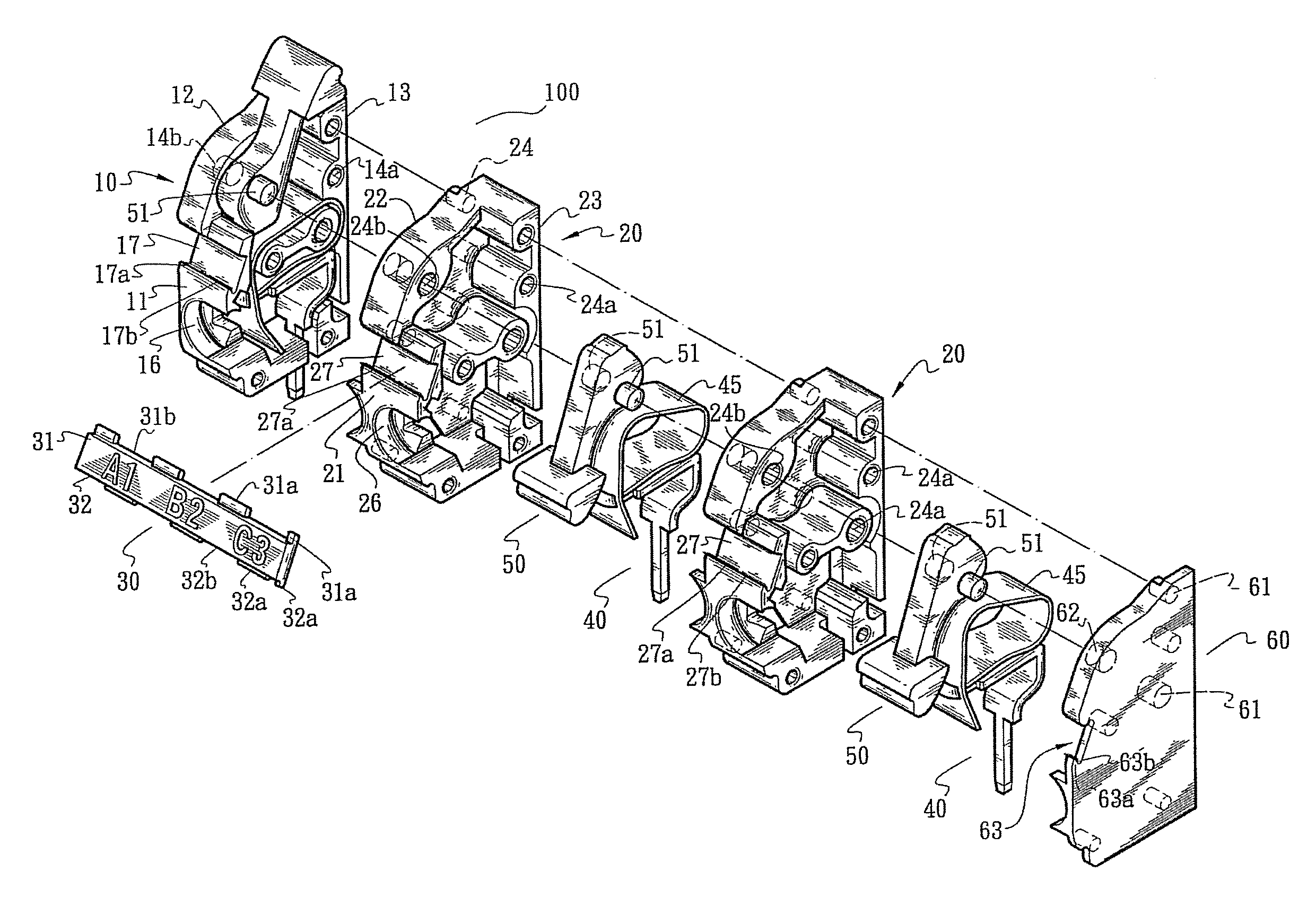
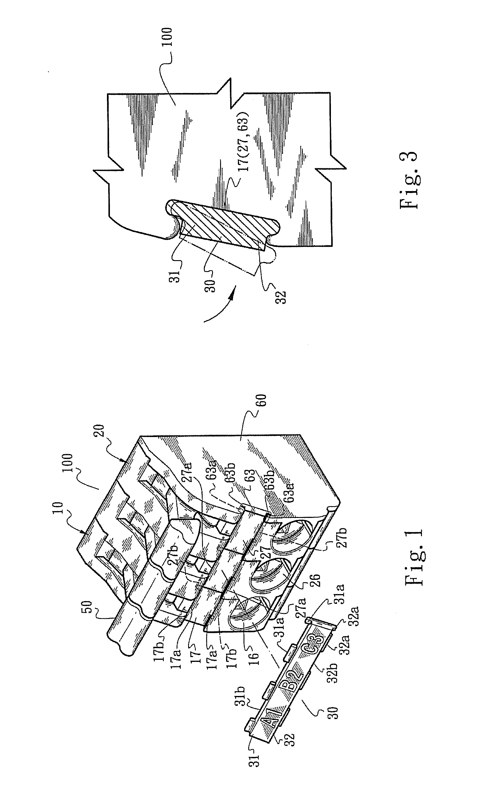
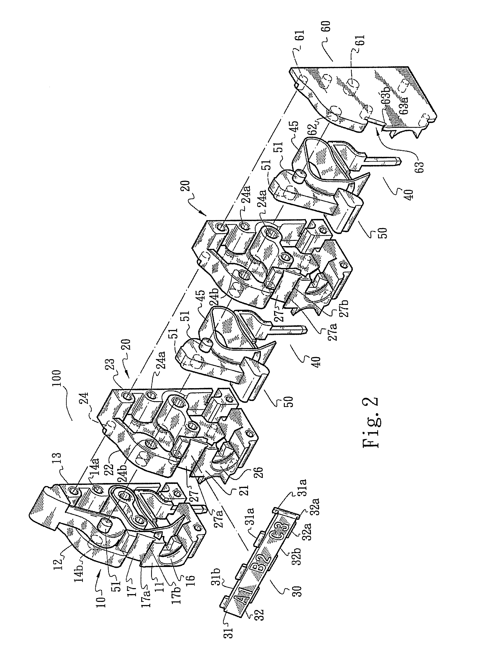
[0031]Please refer to FIGS. 1 and 2. The present invention relates to a connection member and a lead terminal seat structure with the connection member. The lead terminal seat structure of the present invention includes a terminal seat 100, a connection member 30, metal pieces 40 and operation levers 50. FIG. 2 shows the relative positions between these components. Each metal piece 40 includes a leaf spring 45. Basically, the arrangement of the metal pieces 40, the leaf springs 45 and the operation levers 50 pertains to prior art and thus will not be further described hereinafter.

[0032]In a preferred embodiment, the terminal seat 100 is made of plastic material in the form of an insulation housing. The terminal seat 100 includes a first casing 10 (defined as left casing), a second casing 20 (defined as right casing) and a subsidiary sidewall 60. It should be noted that the subsidiary sidewall 60 can be alternatively directly assembled with the first casing 10. Each of the casings 10...


PUM


Abstract

A connection member and a lead terminal seat structure with the connection member including a terminal seat and a connection member. The connection member has a first edge and a second edge, which are formed with alternately arranged depression sections and protrusion sections. The terminal seat has a recess formed with ridge sections and through sections in adjacency to the ridge sections. The ridge sections and the through sections are arranged corresponding to the depression sections and protrusion sections of the connection member with the connection member received in the recess of the terminal seat with the depression sections and the protrusion sections insert-connected with the ridge sections and the through sections.

Description

BACKGROUND OF THE INVENTION[0001]1. Field of the Invention[0002]The present invention relates generally to a connection member and a lead terminal seat structure with the connection member.[0003]2. Description of the Related Art[0004]A conventional lead terminal or solderless terminal has an insulation housing (generally made of plastic material) and leaf spring or metal piece enclosed in the insulation housing for pressing and electrically connecting with a lead inserted in the lead terminal. For example, U.S. Pat. No. 6,689,955 B2 entitled “connecting device with a connection spring operated by a cam” discloses a typical lead terminal.[0005]Such lead terminal is inserted on a circuit board (such as a PC circuit board). The insulation housing of the lead terminal has multiple perforations. The leads extending from a machine or equipment can be inserted through the perforations into the housing. The housing defines a cavity in which the leaf spring or metal piece is mounted. The lea...

Claims


Application Information

Patent Timeline
IPC IPC(8): H01R9/22
CPCH01R9/2475H01R4/4836H01R4/48365
Inventor WU, CHIH-YUANTASI, MENG-YEW
Owner SWITCHLAB SHANGHAI
Learn More