
Method and apparatus for using plc-based sensor units for communication and streaming media delivery, and for monitoring and control of power usage of connected appliances

Inactive Publication Date: 2012-03-15
ASOKA USA CORP
View PDF47 Cites 3 Cited by
  • Summary
  • Abstract
  • Description
  • Claims
  • Application Information

AI Technical Summary

Benefits of technology

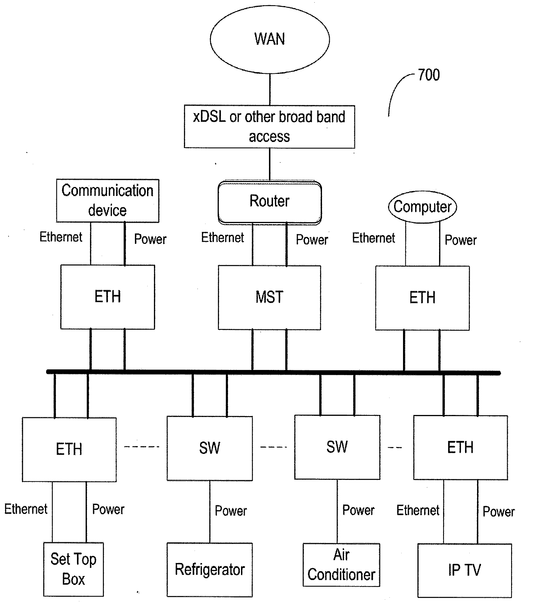
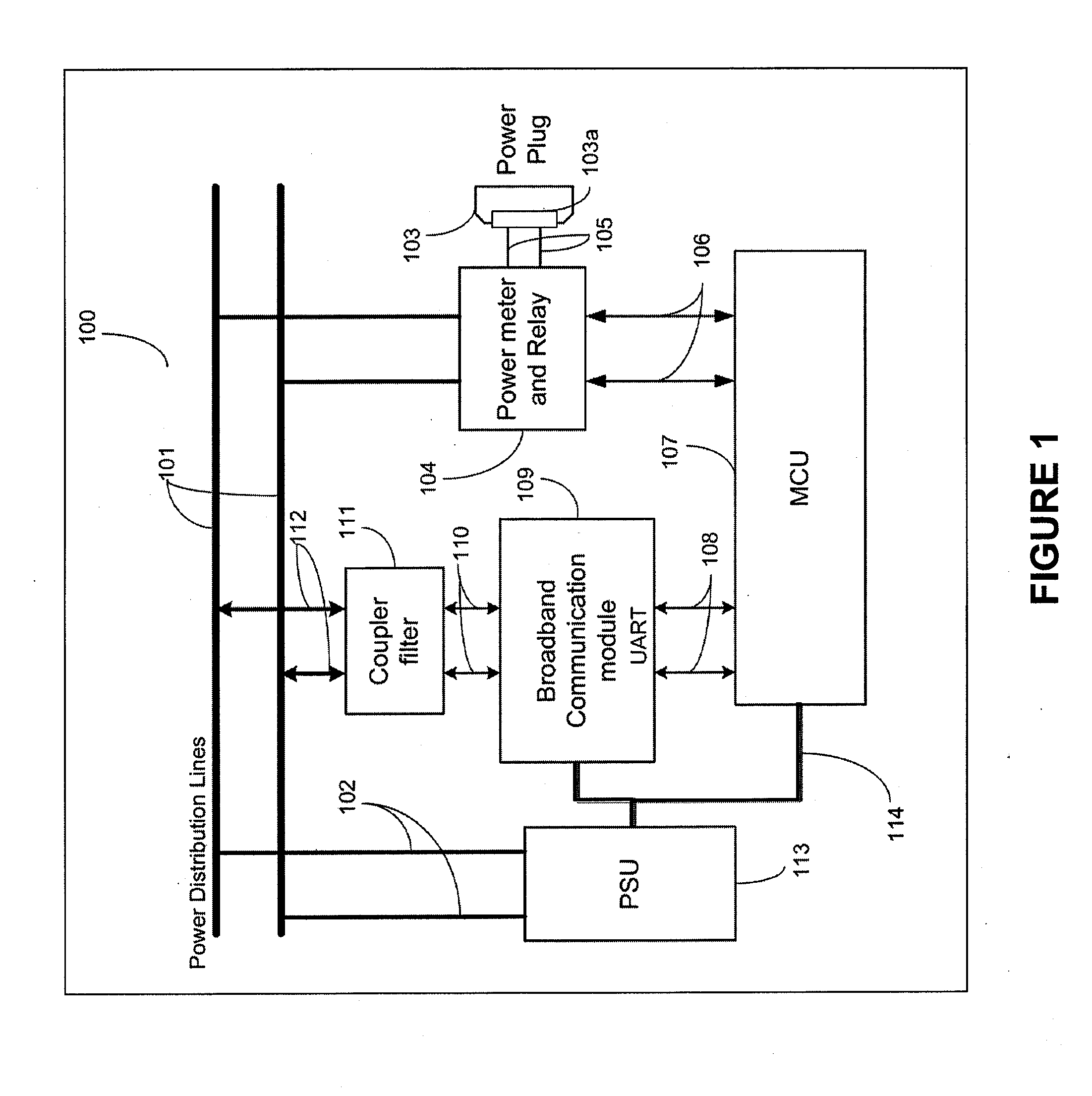
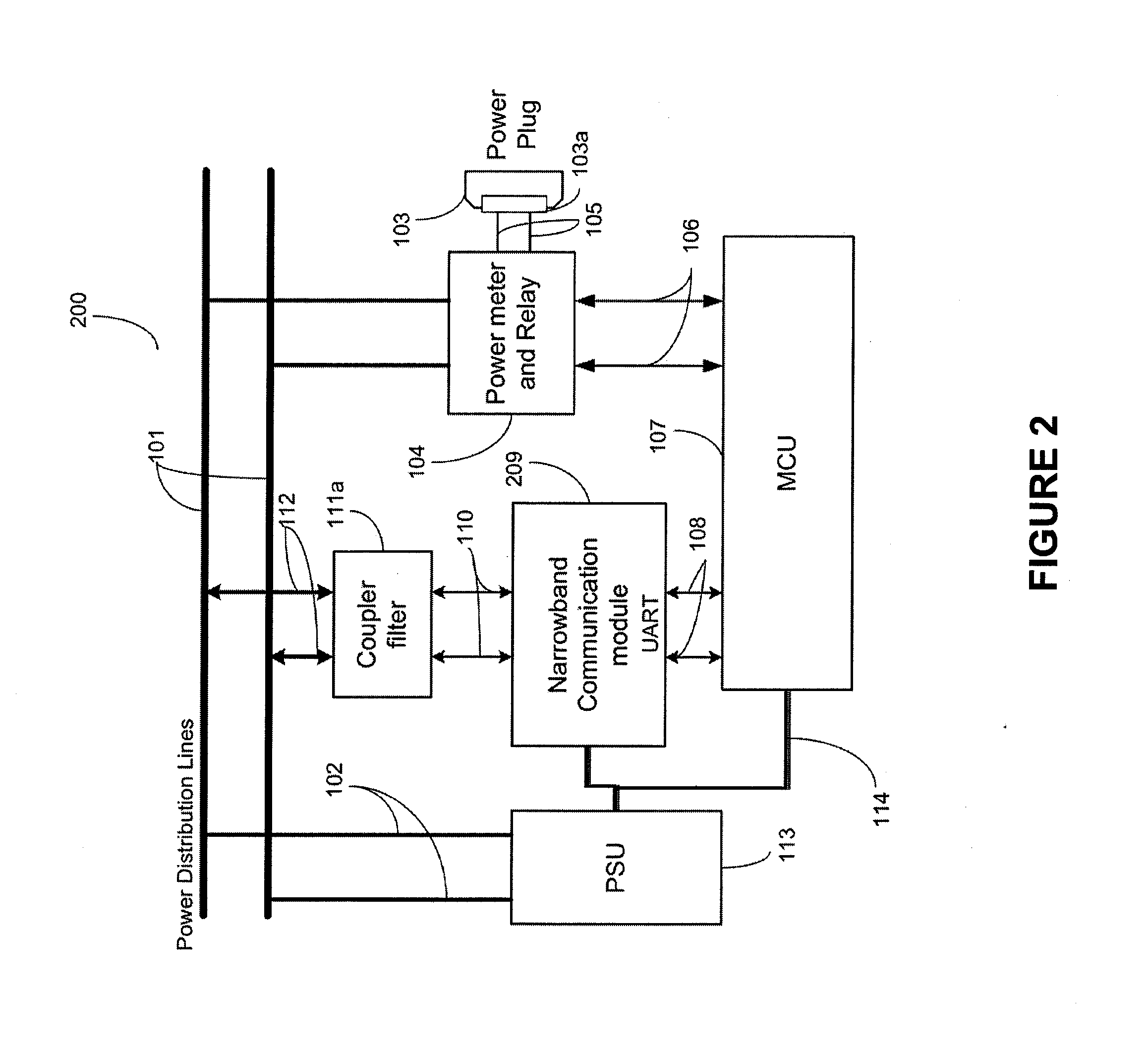
[0006]A method and apparatus are described in which a group of sensors use power line communication (PLC) technology to collect power usage information and enable power management and control, as well as local area networking for a home or office environment. The sensors include an intelligent master sensor and one or more slaves, such as a communication and power management sensor and a power control switch sensor. The master collects and compiles p

Problems solved by technology

The communication of information over power lines has been known from the early 20th century but, due to the higher cost and other limitations for extending the connectivity, the use of such power line communication (PLC) systems has been limited to local area networks within homes, apartments, or offices.
But, due to more efficient competing technologies, the infrastructure for power line communication never developed to make it a mainstream technology.
Despite this early start, power line communication technology has not become a main stream communication technology and the adaptation of this technology has been slow.
This can be attributed to various reasons, including the higher cost of available devices and the lack of suitable devices for communication using power line technology.
Thus, there are no power line devices currently available that can compete efficiently for standard voice and data communication against such technologies as xDSL, cell phones, and satellite communications.

Method used


Image

  • Method and apparatus for using plc-based sensor units for communication and streaming media delivery, and for monitoring and control of power usage of connected appliances
  • Method and apparatus for using plc-based sensor units for communication and streaming media delivery, and for monitoring and control of power usage of connected appliances
  • Method and apparatus for using plc-based sensor units for communication and streaming media delivery, and for monitoring and control of power usage of connected appliances

Examples


Embodiment Construction

[0015]The recent worldwide introduction of new Green technologies and the requirement for end user monitoring and control of a ‘carbon footprint’ of homes and offices has created a need to assess the in-building power usage pattern and magnitude of the usage remotely, and provide the ability to supervise and control the power usage remotely. It is necessary to be able to monitor and control the power usage at a detailed level for the consumer, who is then able to exercise the necessary constraints on use if the proper tools are provided to him. It is also necessary to monitor the usage pattern and collect data on a macro level to develop policies that are beneficial to the overall reduction in ‘carbon footprint’ at the home and office level, as well as on a national level. Empowering the individual and society to exercise the necessary controls by monitoring the power usage is an area where power line communication and control can be effectively and optimally used.

[0016]To this end,...


PUM


Abstract

A group of sensors use power line communication (PLC) technology to collect power usage information and enable power management and control, as well as provide local area networking. The sensors include an intelligent master sensor and one or more slave devices, such as a communication and power management sensor and a power control switch sensor. The master collects and compiles power usage data from the slaves and communicates this data via the web or other communication means to the outside world. The master also receives and distributes instructions for controlling power usage via associated switches in the home or office. These sensors provide integrated sensing and control of home power usage and power management and establish a LAN that has communication capability and that supports streaming media delivery.

Description

BACKGROUND OF THE INVENTION[0001]1. Technical Field[0002]The invention relates to power line networking, with remote power monitoring and control of appliances, within a local area network. More particularly, the invention relates to reducing the carbon foot print of in-home appliances by using appropriate devices for power monitoring, data collection, and control and communication over power lines.[0003]2. Description of the Background Art[0004]The communication of information over power lines has been known from the early 20th century but, due to the higher cost and other limitations for extending the connectivity, the use of such power line communication (PLC) systems has been limited to local area networks within homes, apartments, or offices. Basic devices for connecting to the power line for communication and power supply have been designed and used to provide service within local area networks (LANs). But, due to more efficient competing technologies, the infrastructure for p...

Claims


Application Information

Patent Timeline
IPC IPC(8): G06F1/28G05B11/01
CPCH04L12/10Y02B60/33H04L12/2825H02J2310/12Y02D30/50Y04S20/20Y02B70/30Y02A30/60
Inventor XIA, MINGYAOGRUBEL, ERICCASTELLANO, DAN
Owner ASOKA USA CORP
Learn More