
Ray tracing core and ray tracing chip having the same

a ray tracing chip and ray tracing core technology, applied in the field of 3d graphic processing, can solve the problem of requiring a separate high-performance processor

Active Publication Date: 2012-03-22
SILICONARTS
View PDF10 Cites 63 Cited by
  • Summary
  • Abstract
  • Description
  • Claims
  • Application Information

AI Technical Summary

Benefits of technology

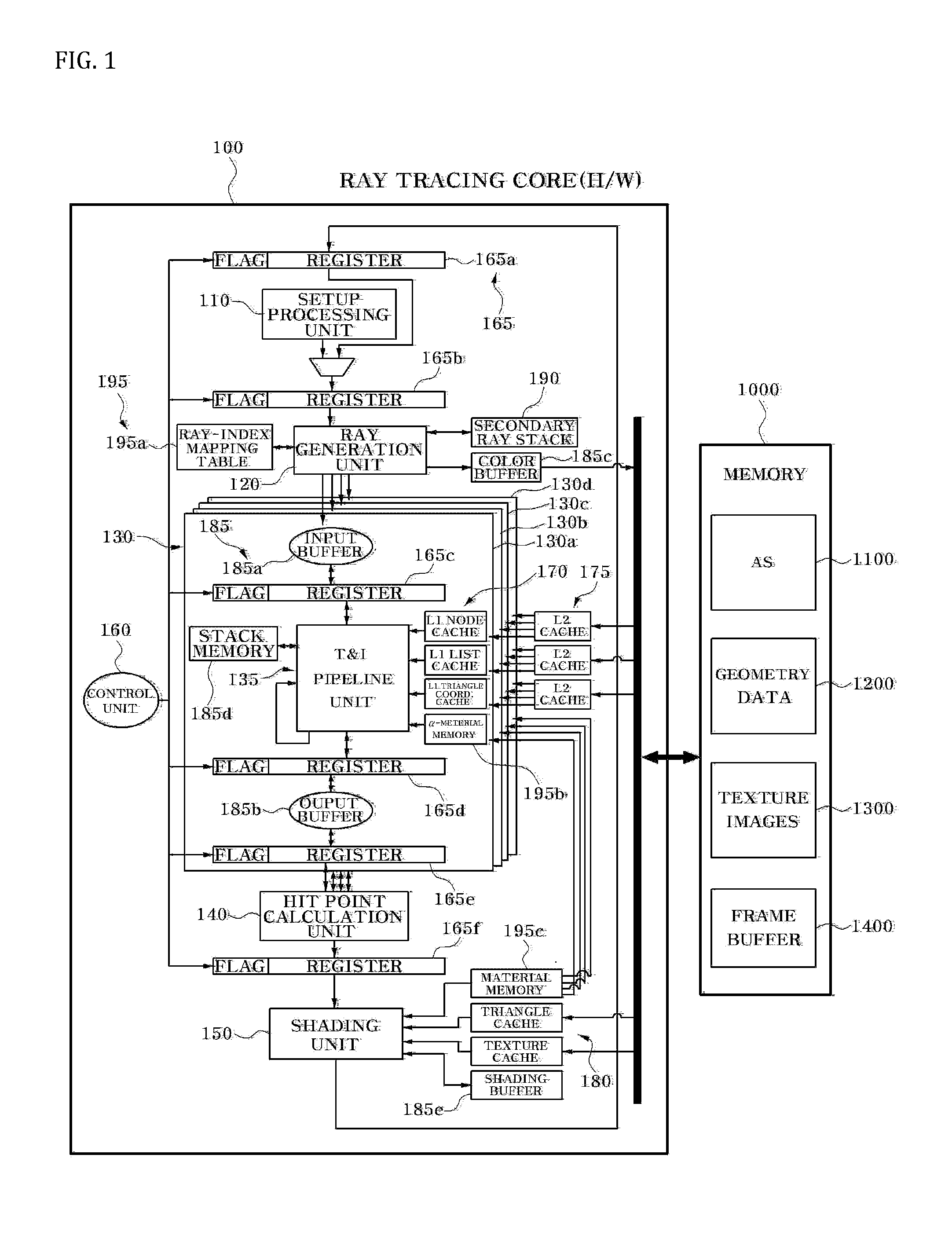
"The patent describes a ray tracing chip that includes a ray generation unit and multiple T&I (Traversal & Intersection) units with MIMD (Multiple Instruction stream Multiple Data stream) architecture. The chip can generate eye rays based on eye ray generation information and shading information, which includes a coordinate value, color value, and shading ray type for a ray-triangle hit point. The chip can then check whether there is a triangle intersected with the eye ray and determine a final color value. The technical effect of this design is that it allows for efficient and accurate ray tracing in a parallel processing manner, resulting in faster and more effective rendering of images."

Problems solved by technology

Generally, the 3-D graphic technology requires a separate high performance processor due to a large amount of computations.

Method used


Image

  • Ray tracing core and ray tracing chip having the same
  • Ray tracing core and ray tracing chip having the same
  • Ray tracing core and ray tracing chip having the same

Examples


Embodiment Construction

[0016]Embodiments of the described technology now will be described more fully with reference to the accompanying drawings, in which embodiments of this technology are shown. This technology may, however, be embodied in many different forms and should not be construed as limited to the embodiments set forth herein. Rather, these embodiments are provided so that this disclosure will be thorough and complete, and will fully convey the scope of this technology to those skilled in the art. Like reference numerals refer to like elements throughout this application.

[0017]It will be understood that, although the terms first, second, etc. may be used herein to describe various elements, these elements should not be limited by these terms. These terms are used to distinguish one element from another. For example, a first element could be termed a second element, and, similarly, a second element could be termed a first element, without departing from the scope of the present invention. As use...


PUM


Abstract

A ray tracing core comprising a ray generation unit and a plurality of T&I (Traversal & Intersection) units with MIMD (Multiple Instruction stream Multiple Data stream) architecture is disclosed. The ray generation unit generates at least one eye ray based on an eye ray generation information. The eye ray generation information includes a screen coordinate value. Each of the plurality of T&I units receives the at least one eye ray and checks whether there exists a triangle intersected with the received at least one eye ray. The triangle configures a space.

Description

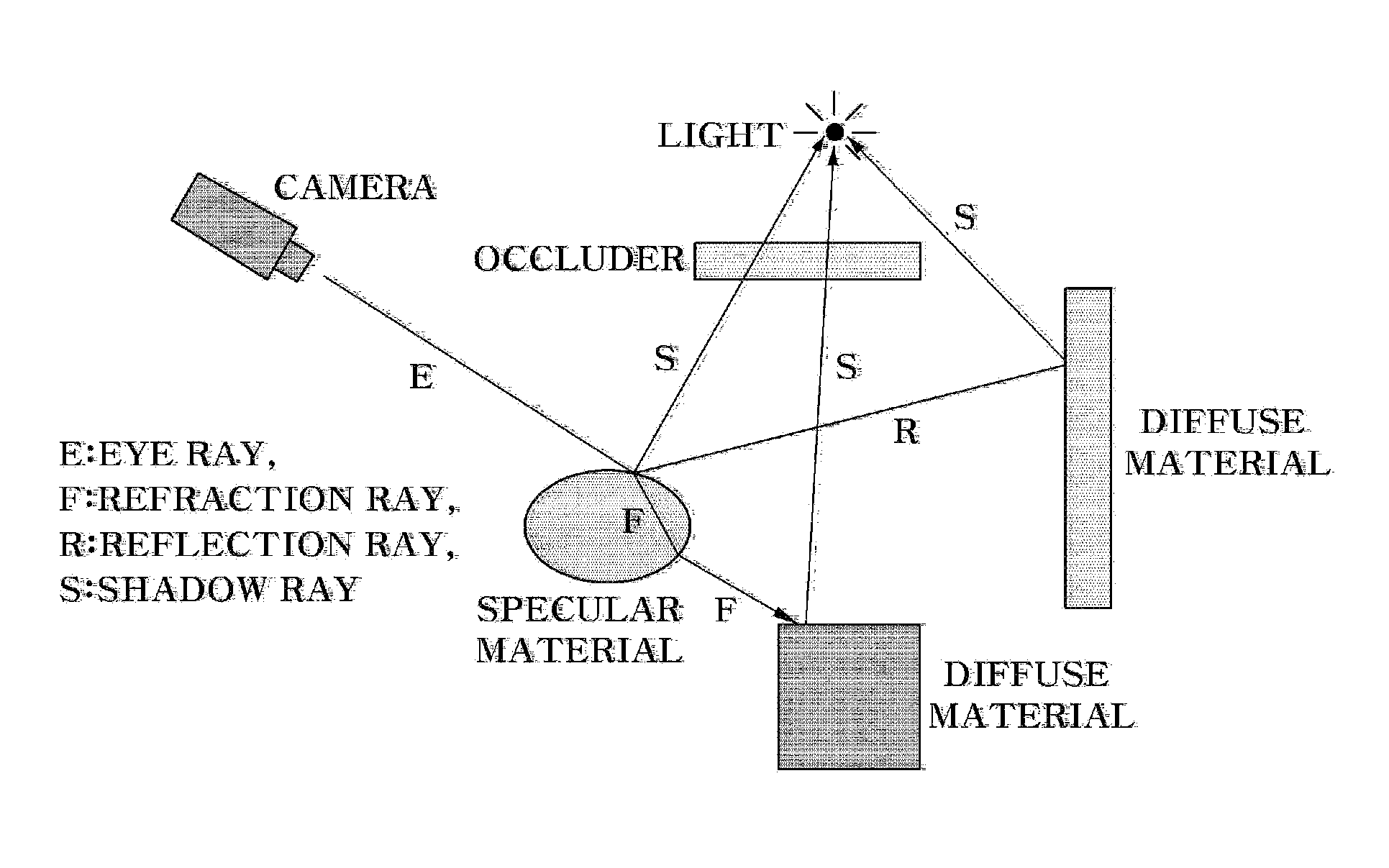
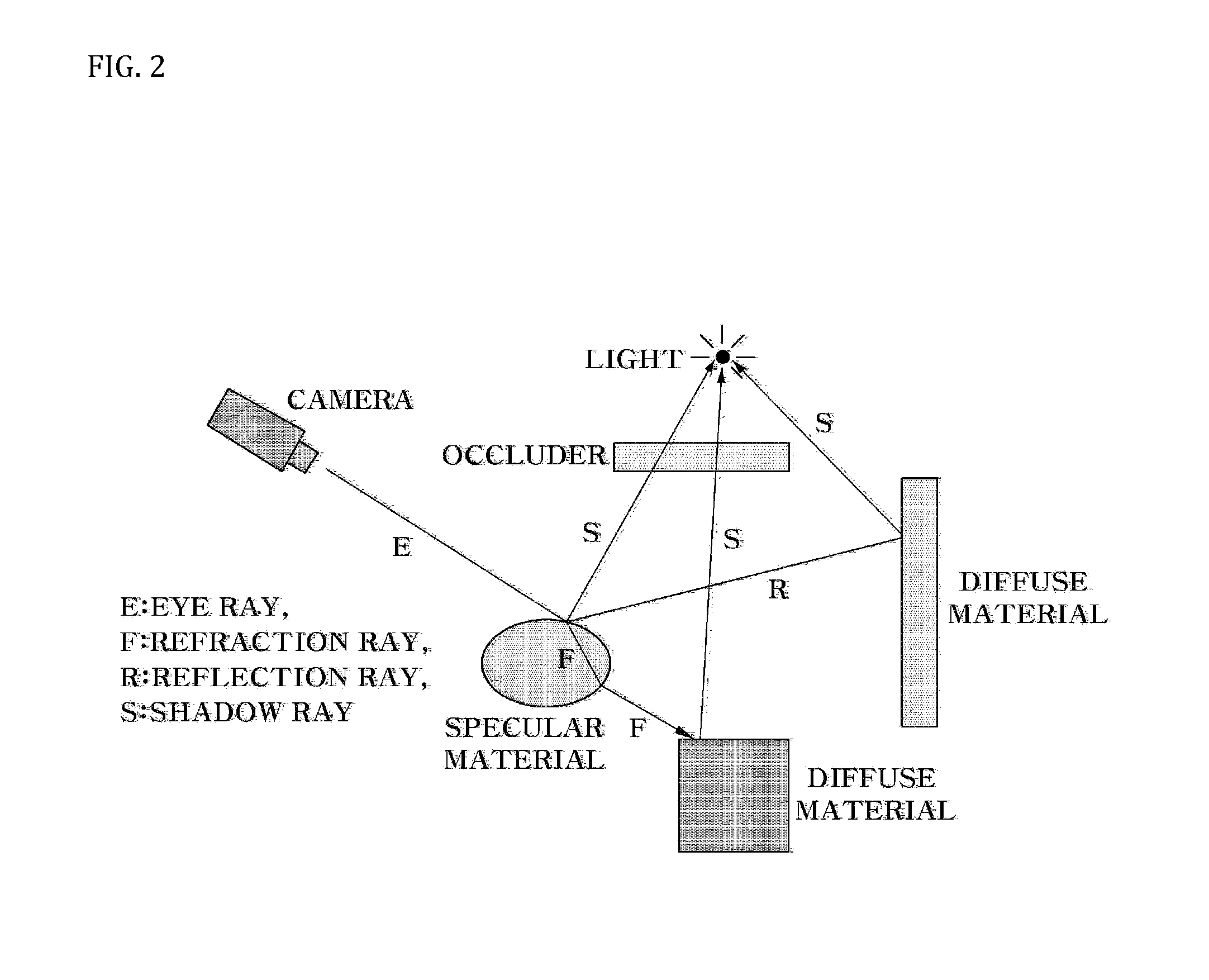
CROSS-REFERENCE TO RELATED APPLICATIONS[0001]This application is the United States National Phase under 35 U.S.C. §371 of PCT International Patent Application No. PCT / KR2010 / 003173, which designated the United States of America, having an International Filing date of May 19, 2010, and claiming priority to Korean Application No. KR 0-2009-0046909, filed May 28, 2009.FIELD OF THE INVENTION[0002]The described technology relates to 3-D graphic processing, and more particularly to a ray tracing core and ray tracing chip having the same.BACKGROUND OF THE INVENTION[0003]Three-dimensional (3-D) graphic technology uses 3-D geometric data representation in a computing system, and is adopted in various industries such as media and game industries. Generally, the 3-D graphic technology requires a separate high performance processor due to a large amount of computations. This is particularly true in ray tracing technology, in which 3-D graphic techniques can simulate very realistic light effects...

Claims


Application Information

Patent Timeline
Patent Type & Authority Applications(United States)
IPC IPC(8): G06T15/06G06T15/00
CPCG06T15/005G06T15/06G06T15/00G06T17/00
Inventor HUR, JIN SUKPARK, WOO CHAN
Owner SILICONARTS
Learn More