Membrane device the membrane of which can be deformed by actuation with a fast response time

a membrane device and fast technology, applied in the field of deformation membrane devices, can solve the problems of direct impact of difficulty on the response time of membrane devices, and achieve the effects of retaining a great amplitude of deformation of the membrane, increasing the response time, and reducing the risk of injury

Active Publication Date: 2012-03-22
WEBSTER CAPITAL LLC
View PDF0 Cites 23 Cited by
  • Summary
  • Abstract
  • Description
  • Claims
  • Application Information

AI Technical Summary

Benefits of technology

[0015]One aim is, in particular, to offer a membrane device having an increased response time, whilst retaining a great amplitude of deformation of the membrane when an actuation occurs.
[0016]Another aim of the invention is to offer a membrane device which, when it has electrostatic means of actuation, enables this great deformation amplitude to be obtained with small energy consumption.
[0017]Yet another aim of the invention is to offer a membrane device which is resistant to impacts, and the effect of the gravity on the fluid does not risk damaging the membrane.

Problems solved by technology

This difficulty has a direct impact on the membrane device's response time.

Method used


Image

  • Membrane device the membrane of which can be deformed by actuation with a fast response time
  • Membrane device the membrane of which can be deformed by actuation with a fast response time
  • Membrane device the membrane of which can be deformed by actuation with a fast response time

Examples


Embodiment Construction

[0037]The present invention will be better understood on reading the description of examples of embodiment given, purely as an indication and in no way limiting, making reference to the annexed illustrations in which:

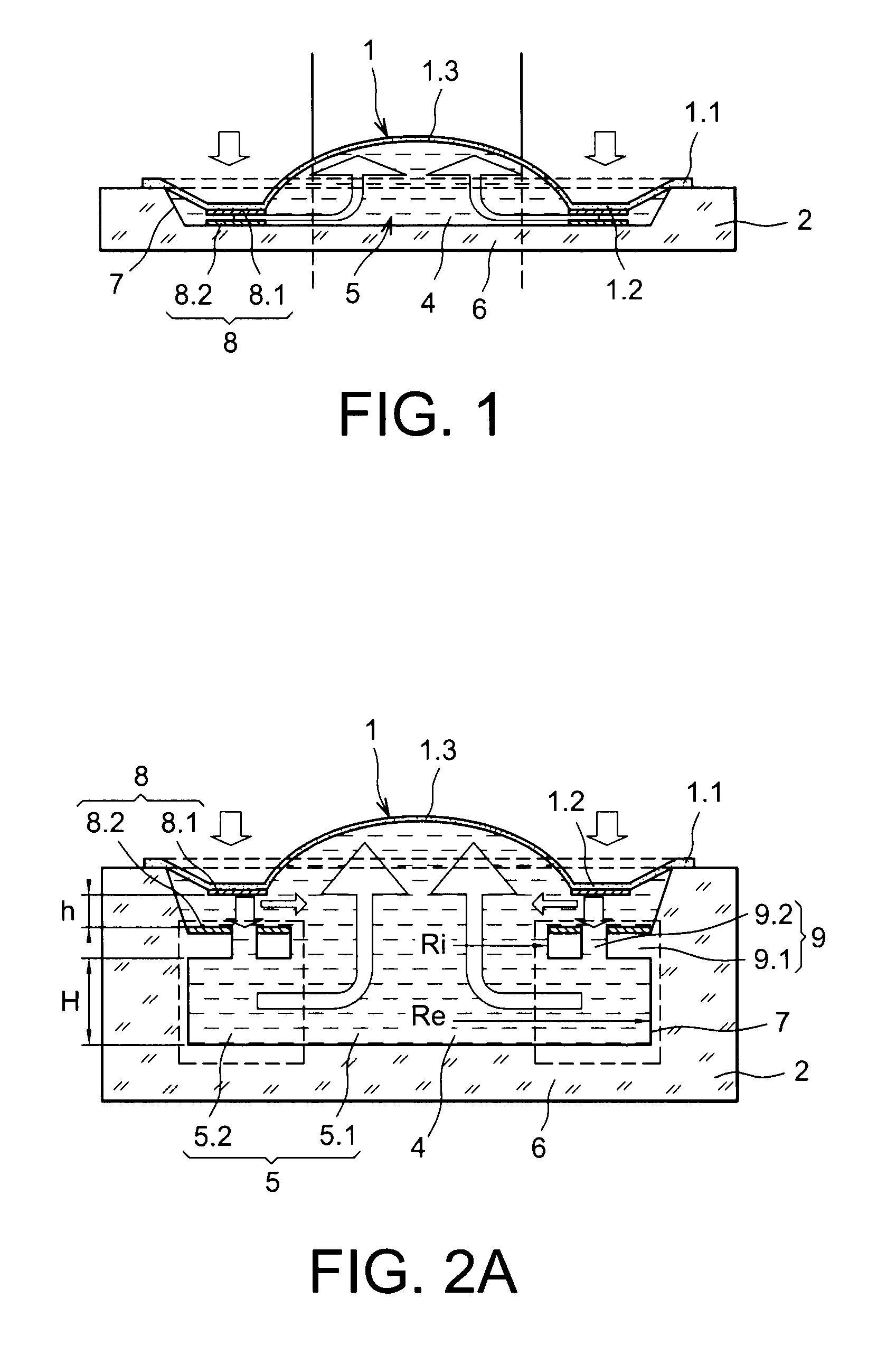
[0038]FIG. 1, previously described, shows in section a membrane device of the prior art;

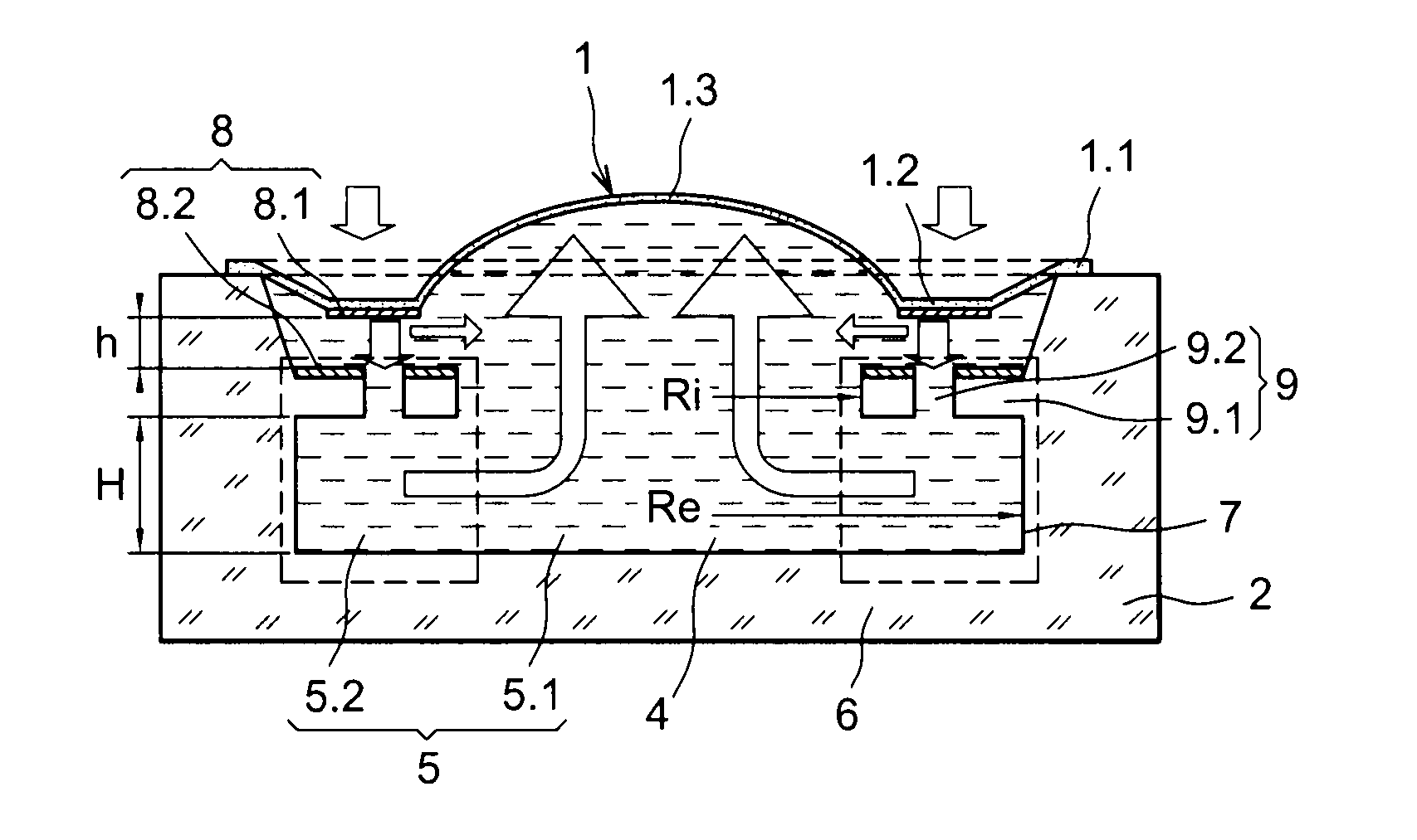
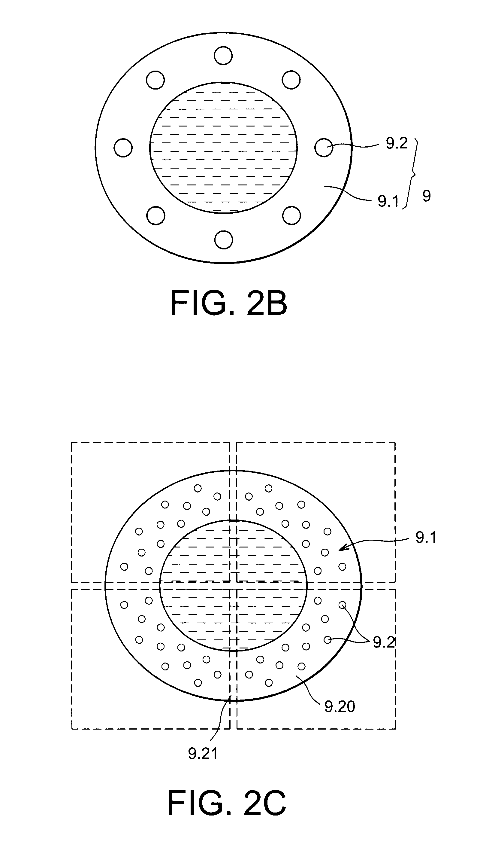
[0039]FIG. 2A shows a membrane device forming the subject of the invention with a forced flow structure with a perforated wall, and FIGS. 2B and 2C show various perforated wall embodiments;

[0040]FIGS. 3A to 3I show in section or as a top view different variants of a forced flow structure cooperating with the bottom of the cavity;

[0041]FIG. 4A shows in section a membrane device forming the subject of the invention with a forced flow structure incorporated in the bottom of the cavity, and with electrostatic means of actuation; FIG. 4B is a top view of the bottom of the cavity;

[0042]FIG. 5A shows in section a membrane device forming the subject of the invention with a forced flow struct...


PUM


Abstract

Device including a membrane and a support defining a cavity containing a fluid, where the membrane includes an anchoring area to the support, a central area able to be deformed following a displacement of fluid and an actuation area between the anchoring and central areas, and means of actuation to apply stress to the membrane in the actuation area and cause a displacement of the fluid to the central area following an actuation. The cavity includes a main chamber in the central area and a peripheral chamber in the actuation area communicating with the main chamber. The peripheral chamber includes at least one forced flow structure favoring the flow of at least a part of the fluid from the peripheral chamber to the main chamber or vice versa following the actuation. A given forced flow structure has no attachment both to the support and to the membrane.

Description

TECHNICAL FIELD[0001]The present invention concerns a device with a deformable membrane trapping fluid and having means of actuating the membrane to adjust its radius of curvature. These devices can be used as variable focal length liquid lenses, liquid lenses for corrections of optical aberrations for active optics, image-stabilisation devices, or variable focal length mirrors. Liquid lenses can be used, for example, in mobile telephones with a photographic device or camera function. Many developments are pending, notably an autofocus function and a zoom function. Another application concerns cameras operating in the infrared spectrum (IR). Progress is slower with integration: in most cases the optics are dissociated from the cameras. Several developments are pending, notably integration of optics (creation of a camera module), integration of the autofocus function, etc. As things stand, the associated technical solutions are not known and have yet to be defined.[0002]In a deformab...

Claims


Application Information

Patent Timeline
Patent Type & Authority Applications(United States)
IPC IPC(8): G02B3/12
CPCG02B3/14G02B13/0075G02B7/08
Inventor BOLIS, SEBASTIEN
Owner WEBSTER CAPITAL LLC
Why Eureka
Try Eureka