Waterproof electronic equipment and assembly method thereof

a technology of electronic equipment and assembly method, applied in the direction of electrical apparatus, electrical apparatus, wave amplification devices, etc., can solve the problems of difficult to obtain a sufficient height dimension, easy loosening of screws, incomplete fastening of attachment screws, etc., and achieve the effect of easy application of sealing materials

Active Publication Date: 2012-03-22
MITSUBISHI ELECTRIC CORP
View PDF7 Cites 45 Cited by
  • Summary
  • Abstract
  • Description
  • Claims
  • Application Information

AI Technical Summary

Benefits of technology

[0007]The invention has been achieved to solve the above described problems, and a purpose of the invention is to provide waterproof electronic equipment in which a circuit board area and a height dimension of a heat generating component can be made larger without degradation of waterproof sealing performance, further having a seal surface structure that enables easy application of a seal material, and an assembly method thereof.

Problems solved by technology

In the above described related art, the circuit board is sandwiched between the step part of the base separately provided inside of the outer peripheral seal part and the flange part of the cover, and thus, there is a problem that, while the area of the circuit board becomes smaller, when it is desired to attach a component with heat generation having a relatively high dimension to the rear surface of the circuit board, it is difficult to obtain a sufficient height dimension.
Further, the sealing gap is adjusted by the height of the planar projection as the mount of the periphery of the circuit board, however, actually, the sealing gap is determined by the height of the contact surface of the attachment screws for tightening the base and the cover together, and, for adjustment of the sealing gap by the height of the planar projection of the base, it is necessary to provide a gap around the contact surface of the attachment screws and a problem that the attachment screws remain incompletely fastened and the screws easily become loose arises.
On the other hand, if the contact surface of the attachment screws is first brought into contact and then the screws are reliably be fastened, a problem that the sealing gap becomes nonadjustable and may be more than the gap determined by dimension variations of the respective parts.

Method used


Image

  • Waterproof electronic equipment and assembly method thereof
  • Waterproof electronic equipment and assembly method thereof
  • Waterproof electronic equipment and assembly method thereof

Examples


embodiment 1

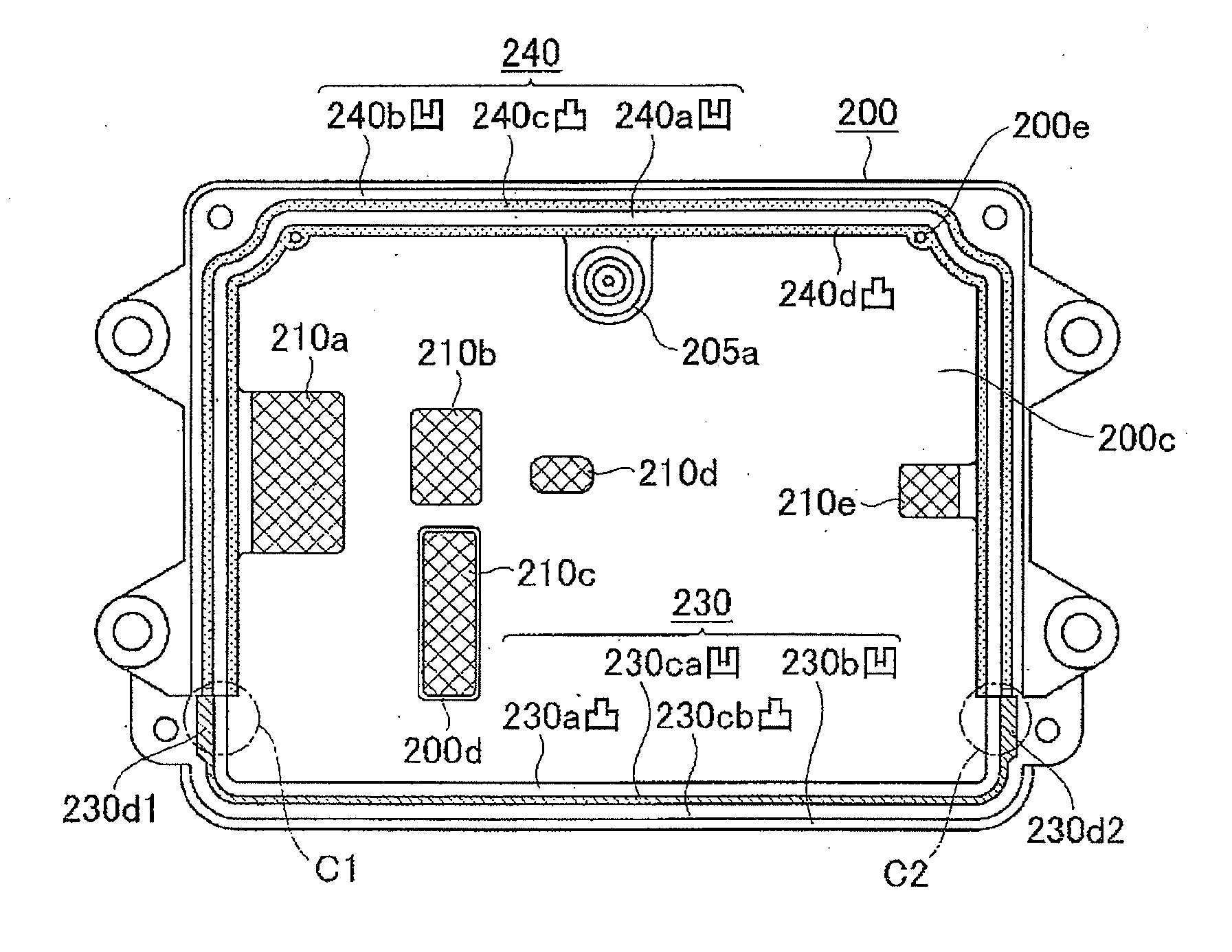
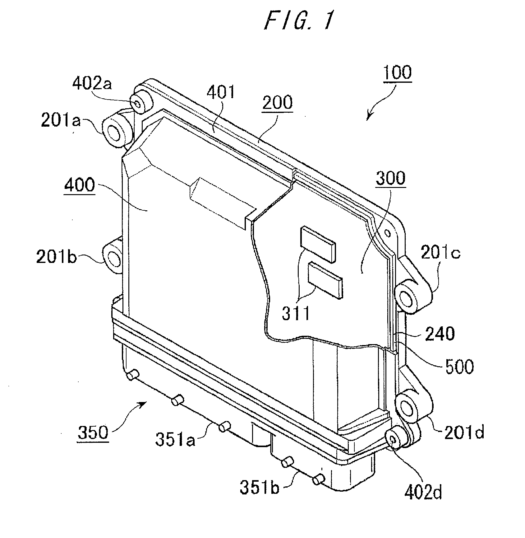
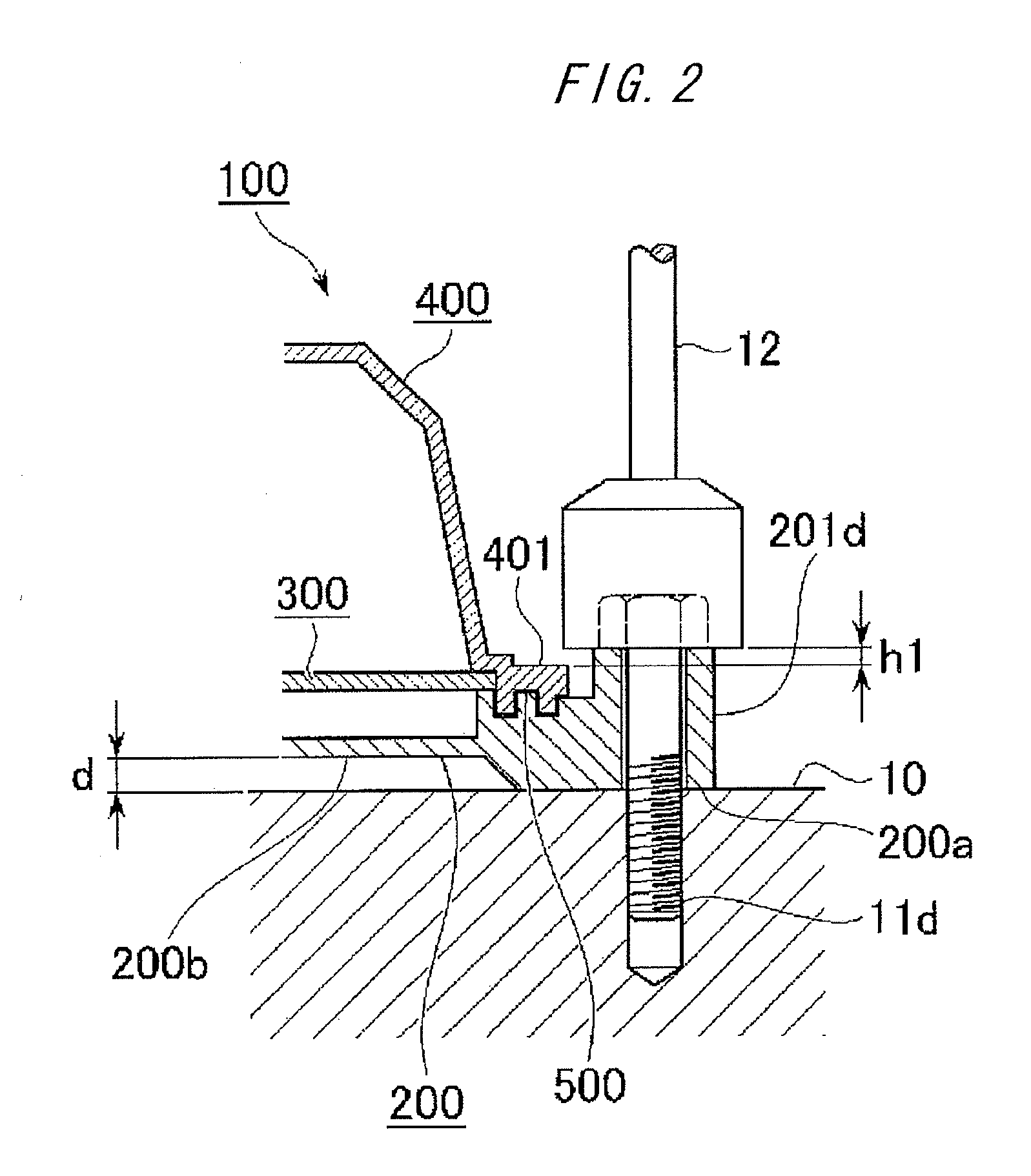
[0040]As below, waterproof electronic equipment according to embodiment 1 of the invention will be described with reference to FIGS. 1 to 16. Here, the case where the electronic equipment is an in-vehicle electronic control unit (hereinafter, simply referred to as “control unit”) will be explained. The contents of the respective drawings have been shown in “Brief Description of the Drawings” as above, and their explanation will be omitted except the case of absolutely necessary. As shown in FIGS. 1 to 6, a control unit 100 includes a base 200 having attachment feet 201a to 201d in four directions and a rectangular shape of aluminum die cast, a circuit board 300 on which plural circuit components 311 and heat generating components etc. (310a to 310c and 310d and 310e (not shown)) shown in FIGS. 4 and 5 are mounted, a cover 400 of resin having a flange part 401 having a flange shape on ends of outer peripheral wall parts in the upper three directions, and a connector member 350 that t...

embodiment 2

[0083]Next, an assembly method of an in-vehicle electronic control unit as waterproof electronic equipment according to embodiment 2 of the invention will be explained with reference to the process chart of FIG. 17. The control unit 100 will be explained appropriately using the respective drawings of embodiment 1. In FIG. 17, step 600 is a start step of an assembly work according to a first assembly method of the control unit 100, and, before the step 600, preparatory steps 601a, 603a, 603b are executed.

[0084]Step 601a is a step of bonding and fixing the ventilation filter 205a to the outside air inlet opening 205c of the base 200 using an adhesive. Step 603a is a step of press fitting and fixing the external connection terminals 352a, 352b in a predetermined number determined for the partition walls 353a, 353b of the connector housings 351a, 351b forming the connector member 350 and press fitting and fixing the snaps 354a to 354c to the connector member 350.

[0085]Step 603b is a ste...

embodiment 3

[0109]Next, an assembly method of an in-vehicle electronic control unit as waterproof electronic equipment according to embodiment 3 of the invention will be explained with reference to FIG. 18. In FIG. 18, step 700 is a start step of an assembly work according to a second assembly method of the control unit 100, and, before the step 700, preparatory steps 703a, 703b, 705a are executed. The preparatory step 703a is a step of press fitting and fixing the external connection terminals 352a, 352b in a predetermined number determined for the partition walls 353a, 353b of the connector housings 351a, 351b and press fitting and fixing the snaps 354a to 354c to the connector member 350.

[0110]Preparatory step 703b is a step of mounting and soldering the heat generating components 310a to 310e and plural circuit components 311 to the circuit board 300, combining the connector member 350 and the circuit board 300 and soldering one ends of the external connection terminals 352a, 352b to lands ...


PUM

PropertyMeasurementUnit
heightsaaaaaaaaaa
thermal conductiveaaaaaaaaaa
heightaaaaaaaaaa

Abstract

Seal surfaces in three directions of a base and a cover are mutually fitted as a first seal part in combination of concave threads and convex threads, and sandwich three sides of a circuit board between an innermost peripheral part convex thread at the base side and an innermost peripheral part concave thread at the cover side. A connector member having a second seal part is fixed to one side of the circuit board, a concavo-convex seal surface between the base and the connector member is located on a low step surface, and the concave and convex threads on the seal surface of the connector member provided on the base pass the concave and convex threads of the seal surface in the three directions each other to be continuous.

Description

BACKGROUND OF THE INVENTION[0001]1. Field of the Invention[0002]The present invention relates to waterproof electronic equipment that can preferably be used as in-vehicle electronic control equipment provided in an engine room or the like, for example, and an assembly method thereof.[0003]2. Background of the Related Art[0004]In in-vehicle electronic control equipment, a waterproof control unit having a connecter housing and a cover fixed to a circuit board as separate structures in which the circuit board is water-tightly held by a base as the first part of a casing, the cover as the second part of the casing, and an end lid as the third part of the casing integrally molded with the connector housing, with the end surface of the connector housing provided on one side of the circuit board exposed to the outside is known. This type of waterproof control unit is more suitable for standardization of the connector part than the form in which the connector housing and the cover are integ...

Claims


Application Information

Patent Timeline
Patent Type & Authority Applications(United States)
IPC IPC(8): H05K5/00H05K13/00
CPCH05K7/20854Y10T29/49002H05K5/0069H05K5/0052
Inventor AZUMI, ISAOHASHIMOTO, KOJI
Owner MITSUBISHI ELECTRIC CORP
Why Eureka
Try Eureka