Method of implementing a magnetically actuated flap seal

a technology which is applied in the field of magnetic actuator and flap seal, can solve the problems of increased maintenance of imaging engine, image degradation, and loss of image quality

Inactive Publication Date: 2012-03-22
EASTMAN KODAK CO
View PDF7 Cites 2 Cited by
  • Summary
  • Abstract
  • Description
  • Claims
  • Application Information

AI Technical Summary

Benefits of technology

[0009]The problem as explained above can be solved by the addition of a flap or door or some other device that covers the slot or slots. The force required to open the slot is provided by the magnetic coupling between the magnetic carrier on one side of the flap and the developer roller magnet on the other side of the flap, although another source of opening or closing force, or both, can be used. A preferred embodiment of the present invention is realized in a method for removing a buildup of a carrier on a scavenger electrode that includes providing a slotted scavenger electrode for collecting the carrier, magnetically directing the carrier toward the slot, at least partially blocking the slot with a flap, which can be a flexible flap or rigid. By accumulating the carrier buildup to a volume sufficient for opening the flap, due to magnetic attractive force increasing for a greater volume, it opens the flap, either by flexing a flexible flap or by rotating a rigid flap, and allows the carrier to travel through the slot. Closing the flap after allowing the carrier to travel through the slot prevents toner dust from an interior region of the printer from passing through the slot in a direction opposite the direction of the carrier traveling through the slot toward the developer station. The flap can be affixed, attached, or connected to the scavenger electrode using any variety of elements such as an adhesive, adhesive tape, nails, rivets, screws, or a hinge. Similarly, the flap can be connected to any of a variety of elements to open or close the flap, such as a spring, a mechanized (motor driven) arm, etc. Blocking the slot can alternatively include completely covering, or sealing, or both, the slot with the flap. The magnetic field is preferably imposed at an angle as close as feasible to about 90° to the flap. A strength of the magnetic field should be about 500 to 700 gauss as measured at the flap. A flexible flap embodiment can take advantage of flap deformation to open the flap, thereby allowing the flap to close by returning to its resting position.

Problems solved by technology

Since this carrier is intended to be reused within the developer station, the loss of carrier can result in degradation of the image due to compromised mixing in developer sump.
This carrier loss can also accumulate to the point where this carrier mass 204 can make contact with the imaging member 202, thereby physically disrupting the image, resulting in a loss of image quality.
These slots can create a problem, because toner dust from the interior of the development station can escape 1301, causing increased maintenance of the imaging engine, higher cost of ownership due to the loss of the toner, and degradation of image quality.

Method used


Image

  • Method of implementing a magnetically actuated flap seal
  • Method of implementing a magnetically actuated flap seal
  • Method of implementing a magnetically actuated flap seal

Examples


Embodiment Construction

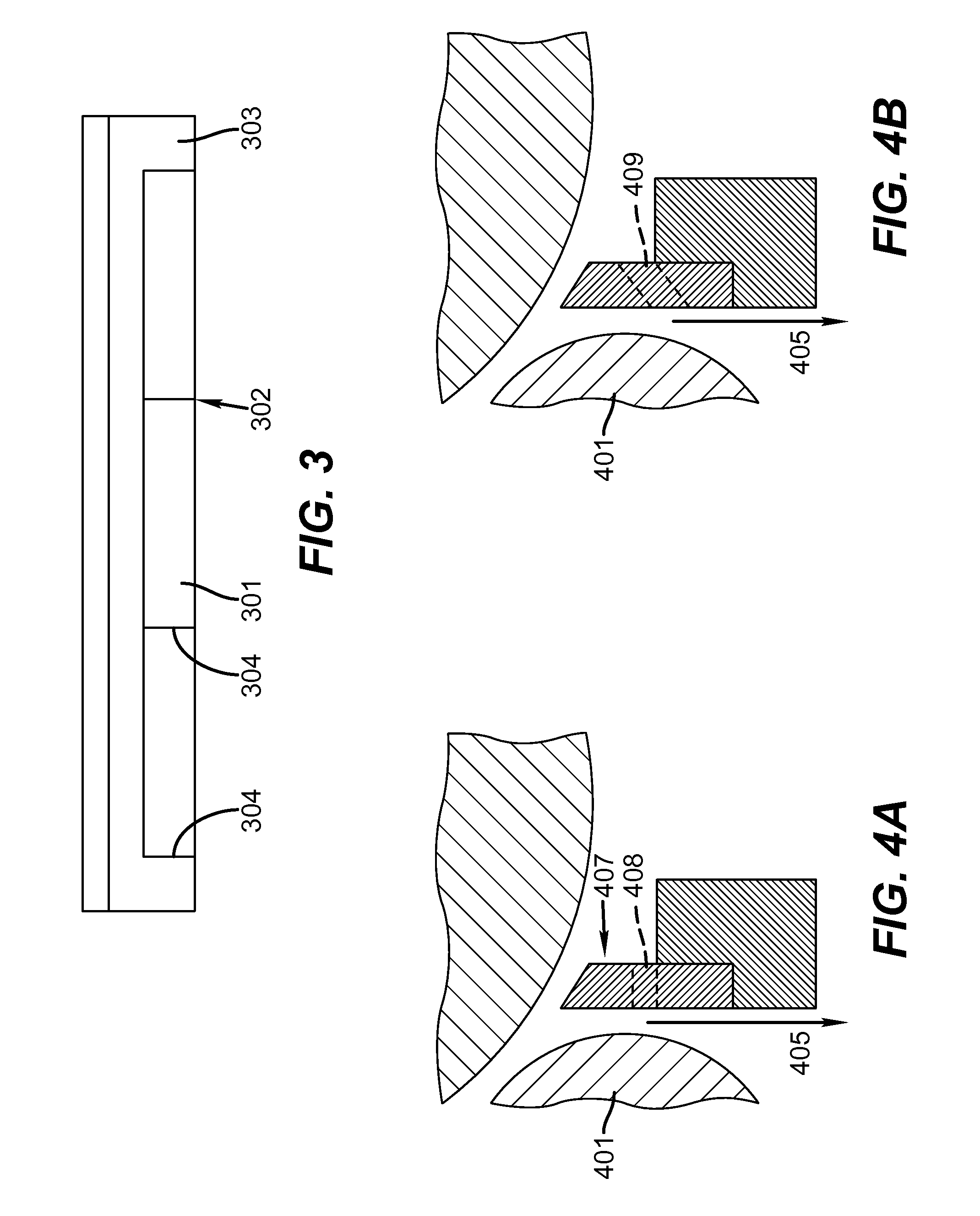
[0026]A preferred embodiment of the present invention provides return of carrier back into a printer's developer station by forming horizontal slots (separated by inter slot webs) through the vertical face of the scavenger electrode, as illustrated in FIG. 3 which shows a front view of the scavenger electrode as seen while looking at the outside vertical face 303. A preferred embodiment of these slots 301, having sidewalls 304, formed through the scavenger electrode comprise slots defined as follows:

[0027]Slot (sidewall) height: range from 3.2 mm to 5.5 mm, or 36% to 61% of the vertical face height of the Scavenger Electrode (approx. 9 mm vertical wall height). The interior and exterior vertical faces of the slots can be referred to as sidewalls.

[0028]Slot Width: range of 20 mm-30 mm.

[0029]Total slot area is 20%-30% of the total area of the inside vertical face of the scavenger electrode. Carrier buildup on the outside vertical face of the scavenger electrode is minimized by reducin...


PUM


Abstract

A method for removing carrier buildup in a slotted scavenger electrode in a printer comprising magnetically attracting the carrier toward the slot, blocking the slot with a movable flap for preventing toner dust from traveling through the slot, opening the movable flap for allowing the carrier to travel through the slot and return to the developer station, then reclosing the movable flap.

Description

CROSS REFERENCE TO RELATED APPLICATION[0001]Reference is made to commonly assigned, co-pending U.S. patent applications:[0002]Ser. No. ______, by Brown et al., (Docket 96557) filed of even date herewith entitled, “Magnetically Actuated Flap Seal”;[0003]Ser. No. 12 / 827,261 by Brown et al. (Docket 96396) filed Jun. 30, 2010 entitled “Printer Having An Alternate Scavenger Geometry”;[0004]Ser. No. 12 / 827,305 by Brown et al. (Docket 96397) filed Jun. 30, 2010 entitled “Fabrication Of An Alternate Scavenger Geometry”; and[0005]Ser. No. 12 / 859,549 by Brown et al. (Docket 96065) filed Aug. 19, 2010 entitled “An Alternate Scavenger Geometry that Promotes Carrier Return Back Into the Development Station”, the disclosures of which are incorporated herein by reference in their entireties.FIELD OF THE INVENTION[0006]The present invention pertains to electrographic printers and copiers utilizing developer comprising toner, carrier, and other components.BACKGROUND OF THE INVENTION[0007]Electrograp...

Claims


Application Information

Patent Timeline
Patent Type & Authority Applications(United States)
IPC IPC(8): G03G15/09
CPCG03G21/0047
Inventor BROWN, KENNETH J.RIMAI, DONALD S.
Owner EASTMAN KODAK CO
Why Eureka
Try Eureka