Magnetic chuck

Pending Publication Date: 2021-01-28
SMC CORP
View PDF6 Cites 1 Cited by
  • Summary
  • Abstract
  • Description
  • Claims
  • Application Information

AI Technical Summary

Benefits of technology

The patent text is looking for magnetic chucks that can increase the magnetic flux in the workpiece to hold it with a stronger force.

Problems solved by technology

Attracting a heavy workpiece with a magnetic chuck requires an increased attracting force, but increasing the attracting force is not easy if the workpiece is a thin plate, because magnetic saturation occurs inside the workpiece.
Further, simply choosing a permanent magnet having a large magnetic force leads to an increase in size of the device.

Method used


Image

  • Magnetic chuck
  • Magnetic chuck
  • Magnetic chuck

Examples


first embodiment

[0027]A magnetic chuck 10 of a first embodiment of the present invention will be described referring to FIGS. 1 to 9.

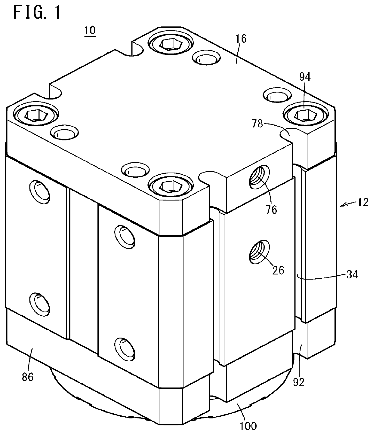
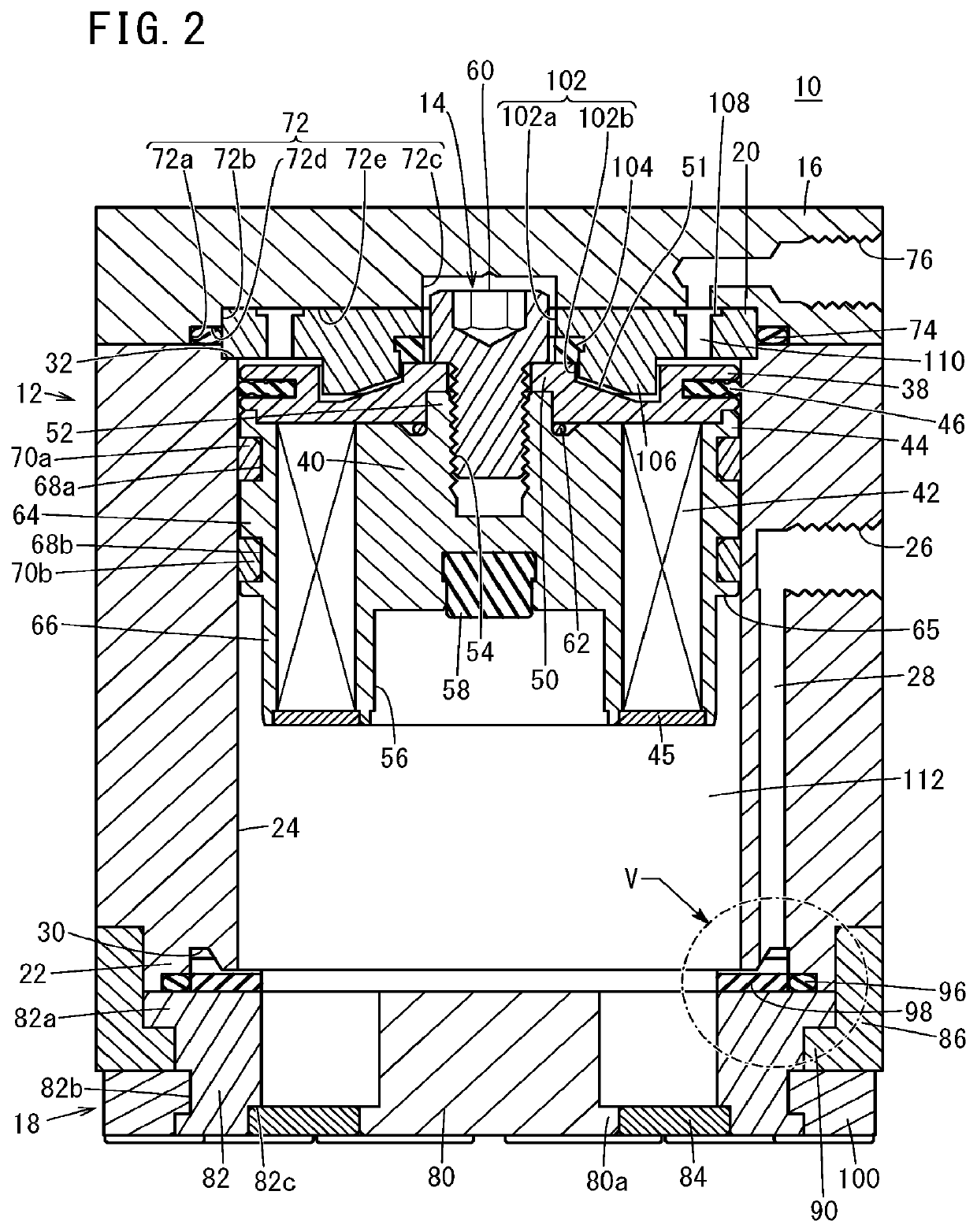
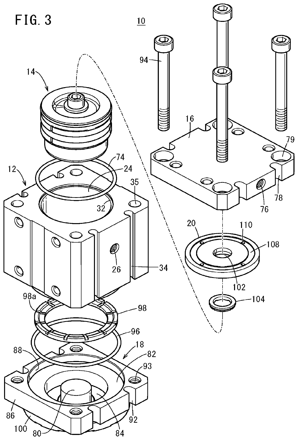
[0028]The magnetic chuck 10 includes a cylinder tube 12, a piston assembly 14, a top cover 16, a bottom cover 18, and a latch yoke 20. The magnetic chuck 10 is attached to an end arm of a robot not shown, for example.

[0029]The cylinder tube 12 is made of a paramagnetic metal such as an aluminum alloy. The cylinder tube 12, except a fitting portion 22 formed at the lower end of the cylinder tube 12, has a rectangular outline in transverse section, and the cylinder tube 12 hence has four side surfaces. The fitting portion 22 of the cylinder tube 12 has a circular outline in transverse section. The cylinder tube 12 has a cylinder hole 24 having a circular cross section and passing through the cylinder tube 12 along its axial direction.

[0030]A first port 26 for supplying and discharging air is formed in one side surface of the cylinder tube 12. The first port 26 connects ...

second embodiment

[0077]Next, a magnetic chuck 120 according to a second embodiment of the present invention will be described referring to FIGS. 10 and 11. The second embodiment differs from the first embodiment in that a long rod 122 is joined to the piston assembly 14 and an adjuster capable of adjusting the position of the movement end of the piston assembly 14 is attached to an exposed end portion of the rod 122. The constituent features of the magnetic chuck 120 of the second embodiment that are the same as or equivalent to those of the above-described magnetic chuck 10 will be labeled with the same reference numerals and will not be described in detail again.

[0078]A tubular protrusion 128 is provided in the center of the top surface of a top cover 126. In the center of the top of the top cover 126 including the tubular protrusion 128, a center hole 130 is formed to continue to the small-diameter portion 72c of the circular recess 72, and the rod 122 is inserted and supported in the center hole...


PUM


Abstract

A magnetic chuck has a piston assembly that contains a cylindrical permanent magnet and a core yoke. The piston assembly is movable inside a cylinder tube. The permanent magnet is provided on the outer periphery of the core yoke and is magnetized in the radial direction.

Description

TECHNICAL FIELD[0001]The present invention relates to a magnetic chuck that attracts and holds a workpiece by means of a force of a permanent magnet.BACKGROUND ART[0002]Magnetic chucks are conventionally known in which a permanent magnet is joined to a piston inside a cylinder and displaced together with the piston (for example, refer to Japanese Laid-Open Utility Model Publication No. 51-102174). In such a magnetic chuck, as the piston is displaced by a fluid pressure, the permanent magnet comes close to the workpiece and attracts and holds the workpiece. The workpiece is released when the piston is displaced in the direction away from the workpiece.[0003]Attracting a heavy workpiece with a magnetic chuck requires an increased attracting force, but increasing the attracting force is not easy if the workpiece is a thin plate, because magnetic saturation occurs inside the workpiece. Further, simply choosing a permanent magnet having a large magnetic force leads to an increase in size...

Claims


Application Information

Patent Timeline
IPC IPC(8): B23Q3/154
CPCB23Q3/1546B23Q2703/02B25J15/0608B66C1/04H01F7/04H01F7/0252H01F7/02B25J15/06
Inventor YAJIMA, HISASHISATO, MOTOHIROSASAKI, TSUYOSHIHARA, KOJIKANDA, KOUICHIROU
Owner SMC CORP
Why Eureka
Try Eureka