

Implant overdenture system and implant
a technology of implant and overdenture, applied in the field of implant overdenture system, can solve the problems of high surgical cost, and achieve the effects of increasing magnetic attractive force, facilitating processing, and increasing magnetic attractive for
- Summary
- Abstract
- Description
- Claims
- Application Information
AI Technical Summary
Benefits of technology
Problems solved by technology
Method used
Image

Examples
example 1
[0095]Examples of the implant overdenture system and implant used in the same are hereinafter described referring to FIGS. 1 to 6.
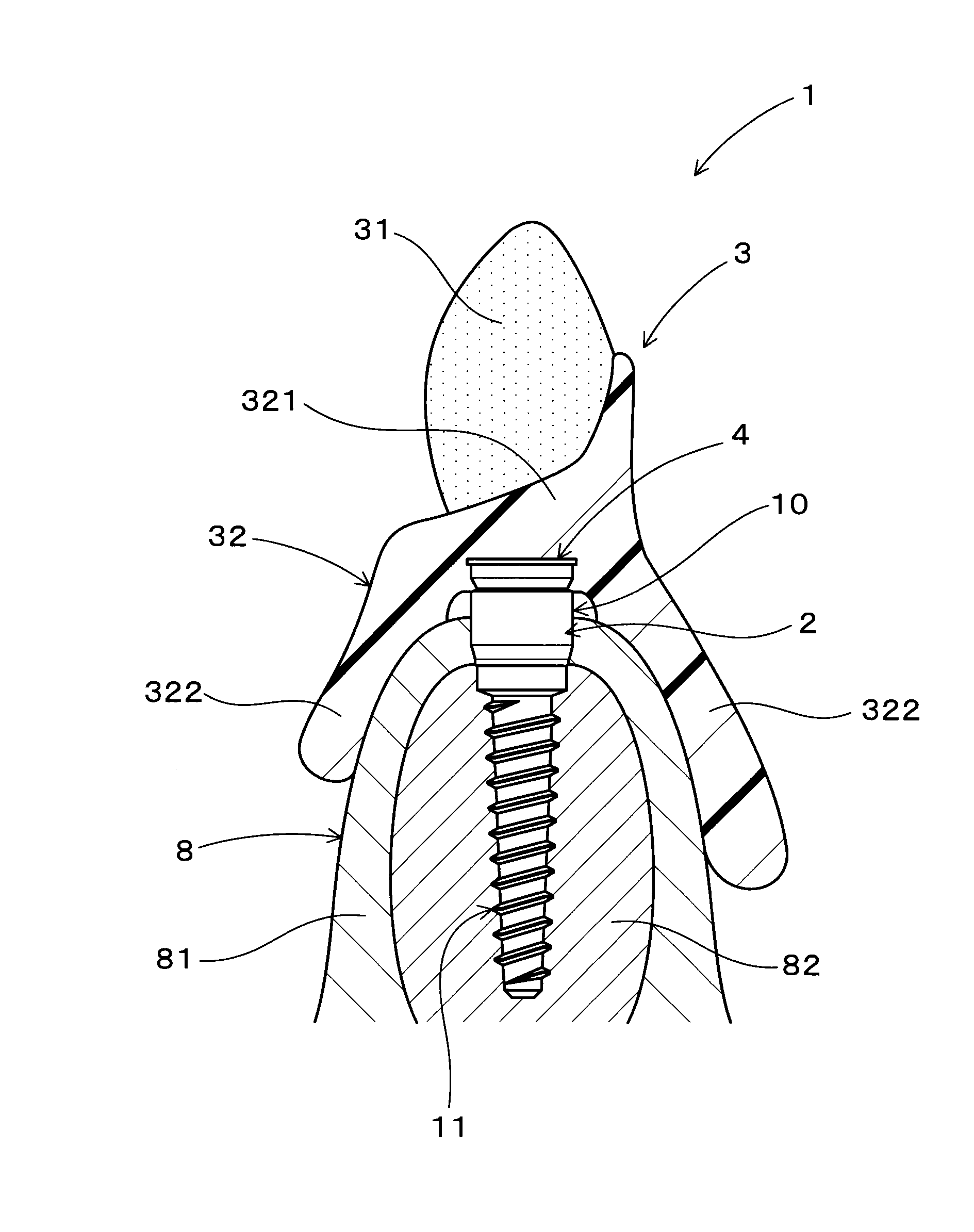
[0096]As illustrated in FIG. 1, an implant overdenture system 1 is used to fix an implant overdenture 3 onto alveolar ridge 8 by the support of dental implants 10.
[0097]The implant overdenture 3 has a plurality of artificial teeth 31, a denture base 32 for the plurality of artificial teeth 31 to be fixed thereto. The denture base 32 is structured to cover gingiva 81 of the alveolar ridge 8. The implant overdenture 3 further has a plurality of magnetic assemblies 4 provided in the denture base 32.
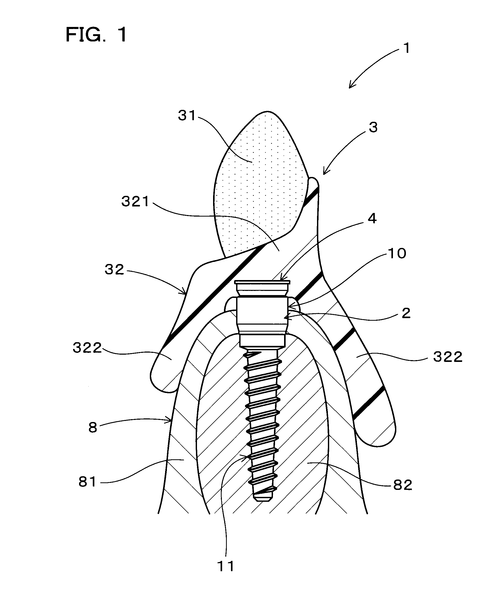
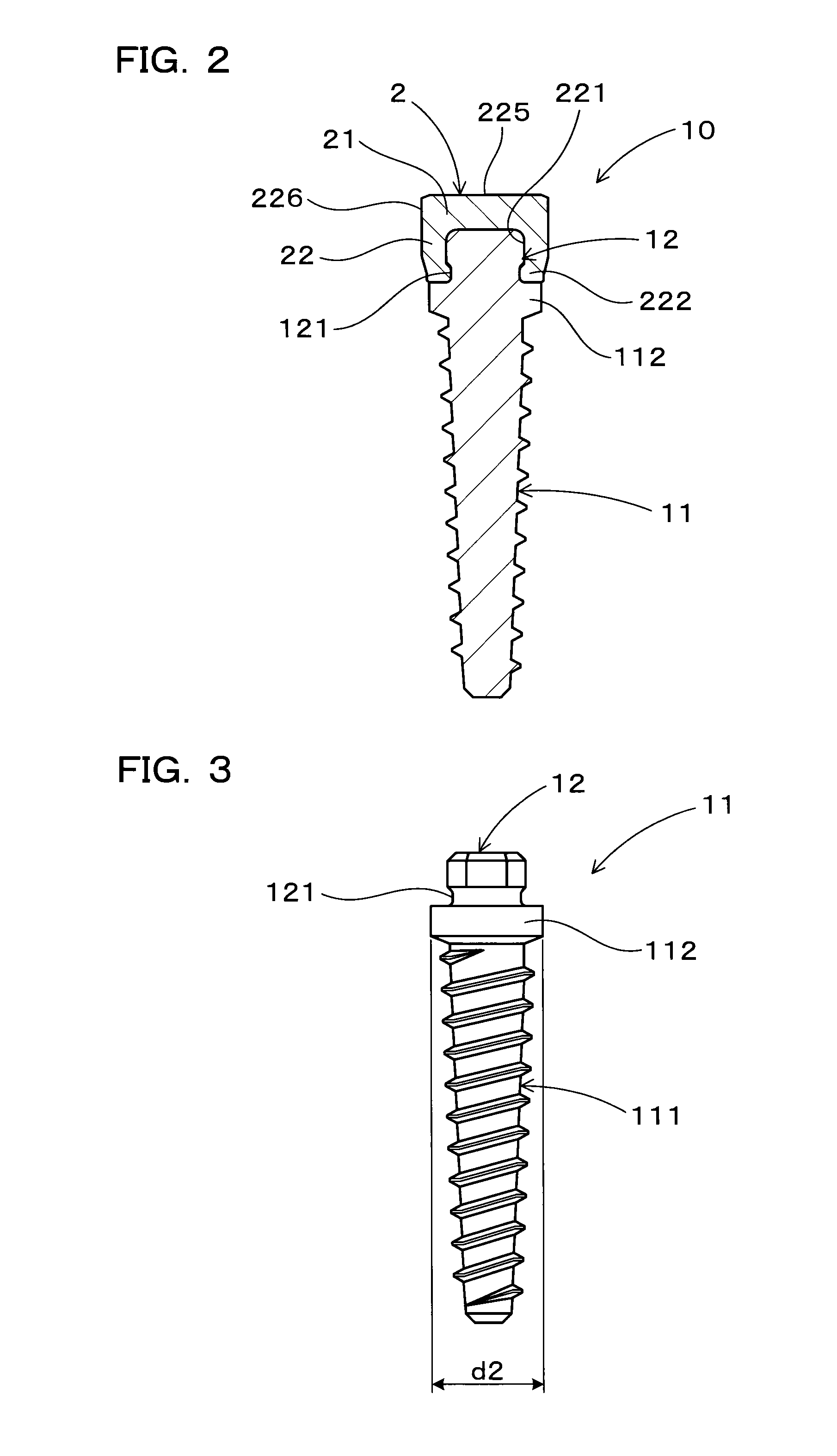
[0098]As illustrated in FIG. 2, the implant 10 includes an implant body 11 formed from a non-magnetic material and configured to be inserted in the alveolar ridge 8, and a keeper 2 formed from a magnetic material and provided at one end of the implant body 11 so as to expose from the alveolar ridge 8. The keeper 2 and the magnetic assembly 4 constitute a magnetic ...
example 2
[0139]This example presents modified shapes of the insert portion 12 and the fallen insert portion 221 of the implant 10 according to Example 1.
[0140]As illustrated in FIG. 7 (a), the insert portion 12 of the implant body 11 has a fastening-engaging portion 123 having a regular hexagonal shape when viewed from upward, and an external thread portion 122 formed on the upper surface of the fastening-engaging portion 123. The external thread portion 122 has a cylindrical shape with threads formed on an outer peripheral side surface thereof.
[0141]As illustrated in FIG. 7 (b), an internal thread portion 223 is formed correspondingly to the external thread portion 122 on the inner peripheral surface of the fallen insert portion 221 of the keeper 2. Provided at an opening end part of the fallen insert portion 221 is an enlarged opening 224 that can accept therein the fastening-engaging portion 123 of the insert portion 12.
[0142]To plant the implant 10 in the alveolar ridge 8 according this ...
example 3
[0145]This example presents a modified structure of the magnetic assembly 40 in the implant overdenture system 1 of Example 1.
[0146]As illustrated in FIGS. 8 and 9, this magnetic assembly 40 has a permanent magnet 401, a pair of yokes 402 provided on two lateral sides of the permanent magnet 401, and a shield case 404 that covers most of a surface of the permanent magnet 401 except parts of the surface where the pair of yokes 402 is provided.
[0147]As illustrated in FIG. 9, the permanent magnet 401 is magnetized so that a direction of magnetic poles (N (north) and S (south) poles) (a direction illustrated with an arrow in the drawing) is coincident with a direction where the pair of yokes 402 and the permanent magnet 401 are juxtaposed. The permanent magnet 401 is in the form of a hexagonal block when viewed in the direction of juxtaposition.
[0148]The shield case 404 is formed from a non-magnetic material and covers the surface of the permanent magnet 401 situated in a direction orth...
PUM
 Abstract
Description
Claims
Application Information