Methods and Systems for Interbody Implant and Bone Graft Delivery

a technology of interbody implants and bone grafts, applied in the field of spinal implants, can solve the problems of limiting the fusion area achieved, many known procedures for spinal fusion, still more invasive than desired, and many known procedures do not provide the level of control over bone delivery and placement, so as to improve the control of bone graft material delivery and/or placement, reduce approach related morbidity, and reduce the effect of approach related morbidity

Inactive Publication Date: 2012-03-22
FARLEY DANIEL K +3
View PDF0 Cites 28 Cited by
  • Summary
  • Abstract
  • Description
  • Claims
  • Application Information

AI Technical Summary

Benefits of technology

[0008]It is therefore one object of the present invention to provide a spinal implant system that reduces approach related morbidity, allows for more bone graft placement and / or provides improved control of the delivery and / or placement of bone graft material.

Problems solved by technology

Most of these cages are limited to only a few cubic centimeters of bone graft material thus limiting the fusion area achieved.
Many known procedures for spinal fusion, however, still are more invasive than desired.
Additionally, many known procedures do not provide the level of control over the delivery and placement of the bone graft material as could be desired.
Additionally, current interbody devices only allow for a limited application of bone material (i.e., cages), and because of their relative size place the neural elements at risk during placement, often resulting in undersized implants being placed.

Method used


Image

  • Methods and Systems for Interbody Implant and Bone Graft Delivery
  • Methods and Systems for Interbody Implant and Bone Graft Delivery
  • Methods and Systems for Interbody Implant and Bone Graft Delivery

Examples


Embodiment Construction

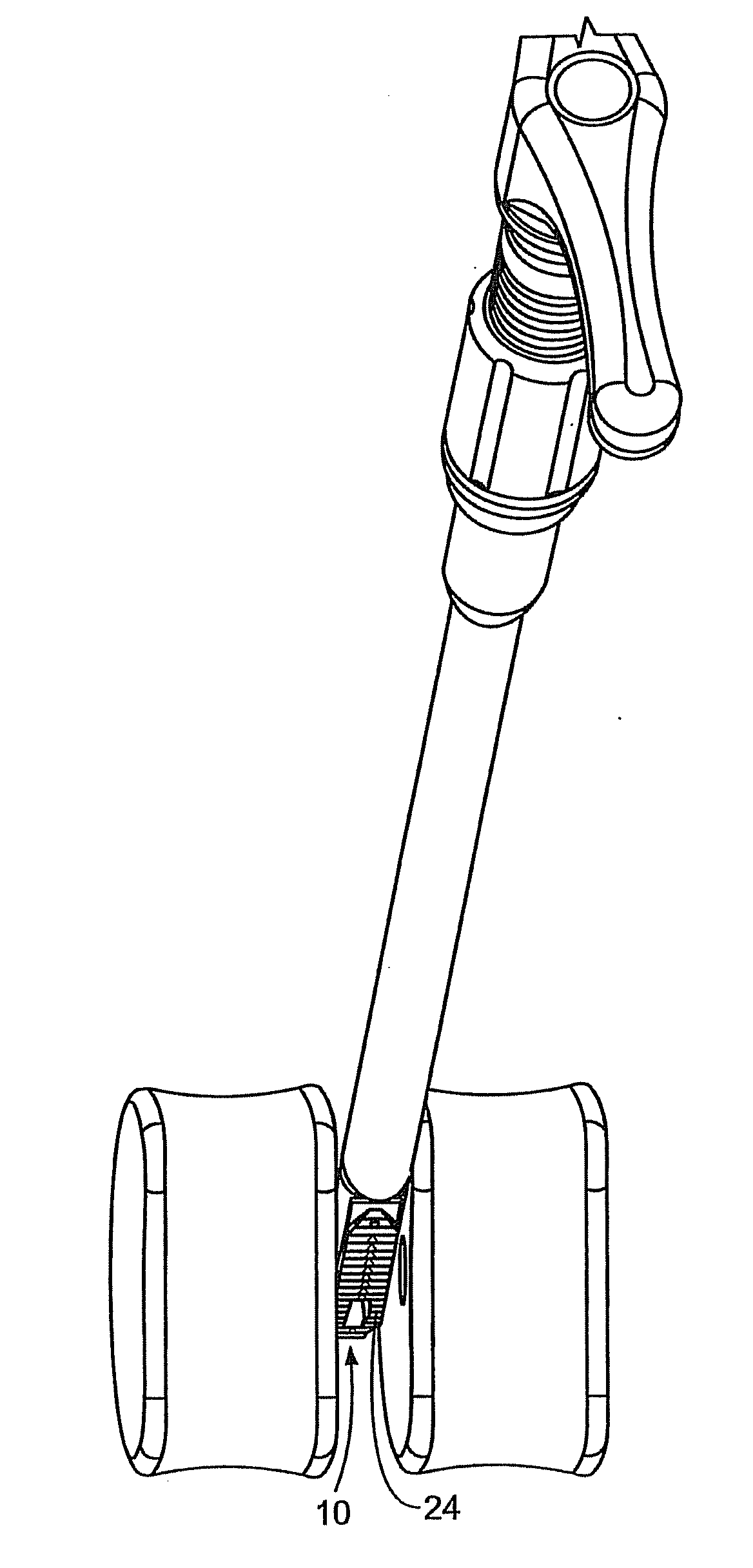
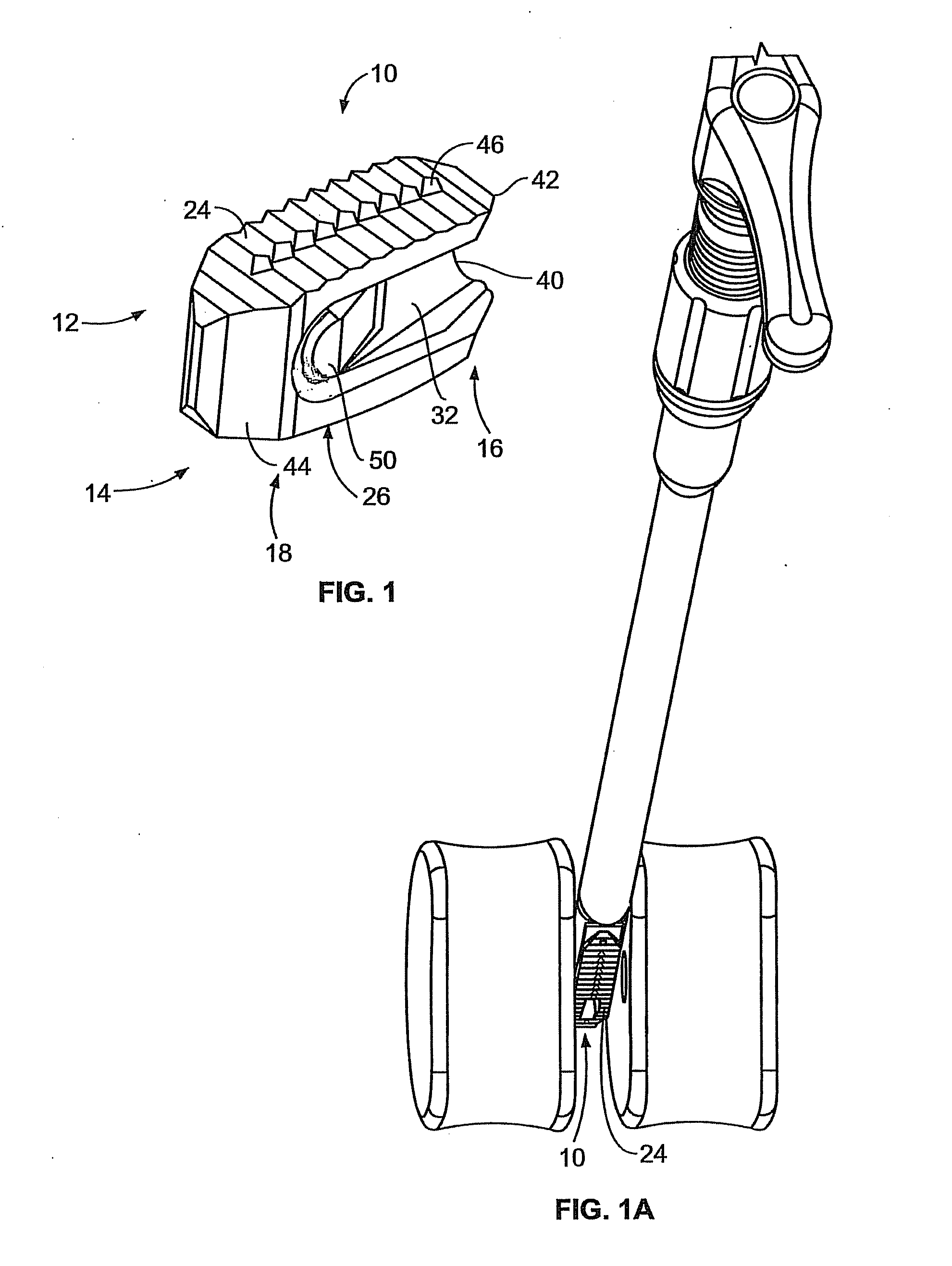
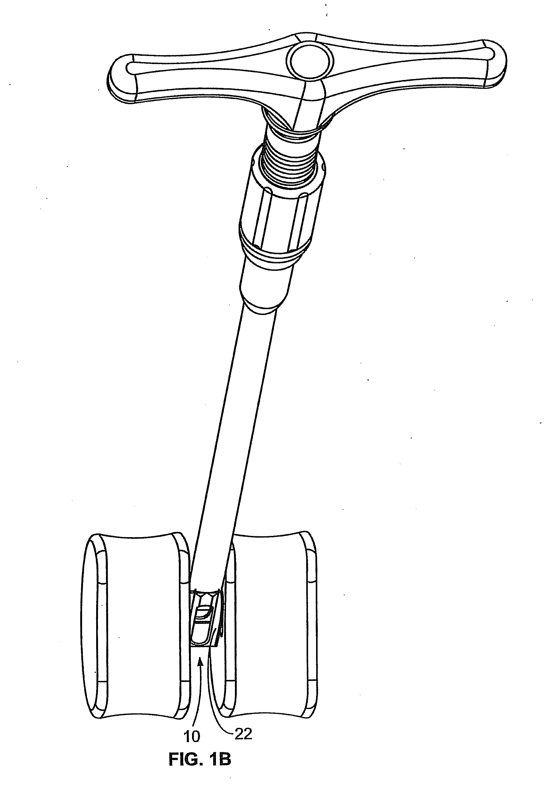
[0038]FIG. 1 illustrates a perspective view of a spinal implant, or spacer, 10; FIG. 2 illustrates a side view of the spacer 10; FIG. 3 illustrates a top view of the spacer 10; and FIG. 4 provides an end view (looking from the proximal end) of the spacer 10. The spacer 10 is sized and adapted to maintain a desired spatial relationship between adjacent vertebrae. Different sizes of spacers are used to accommodate different procedures and / or sizes of patient anatomy. The spacer 10 may, for example, be made of PEEK (polyether ether ketone), titanium, carbon fiber, bone allograft, or a plurality of materials. The spacer 10 may, for example, be solid in certain embodiments, and, in other embodiments, include a hollow portion or portions. The spacer 10 includes a top side 12 and a bottom side 14. (The spacer 10 illustrated in FIGS. 1-4 is symmetric, so “top” and “bottom” sides may be interchangeable). Alternatively, the spacer can be of greater height distally to allow for lordotic disc h...


PUM


Abstract

A spacer for implantation between adjacent vertebrae is provided. The spacer includes a distal end and a proximal end. The spacer also includes top and bottom surfaces spaced by sides. The top and bottom surface define a height, and the sides define a width. Each of the sides of the spacer also includes a depressed region sunk into the side including a sloped surface at least toward the proximal end of the spacer. The distance between the sloped surfaces of the sides decreases proximally to form a wedge having a leading edge proximate to the proximal end of the spacer. The wedge is sized and configured to aid distribution of bone graft material to either side of the wedge, wherein bone graft material is supplied to a site of interest is distributed to at least one side of the wedge.

Description

CROSS-REFERENCE TO RELATED APPLICATION[0001]This application claims priority to “Methods and Systems for Interbody Implant and Bone Graft Delivery,” U.S. Patent Application No. 61 / 377,691, Attorney Docket No. 23079US01, filed Aug. 27, 2010, the entire content of which is hereby incorporated by reference.STATEMENT REGARDING FEDERALLY SPONSORED RESEARCH OR DEVELOPMENT[0002]None.BACKGROUND OF THE INVENTION[0003]The present invention relates to systems and methods for providing spinal implants, for example, to be used in connection with spinal fusion.[0004]Spinal fusion is a surgical procedure that fuses two or more vertebrae together using bone graft materials supplemented with devices. Spinal fusion may be performed for the treatment of chronic neck and / or back pain, trauma, and neoplasms. Spinal fusion can be used to stabilize and eliminate motion of vertebrae segments that may be unstable, or move in an abnormal way, that can lead to discomfort and pain. Spinal fusion may be perform...

Claims


Application Information

Patent Timeline
Patent Type & Authority Applications(United States)
IPC IPC(8): A61F2/44
CPCA61F2/447A61F2310/00359A61F2002/30266A61F2002/30281A61F2002/305A61F2002/30736A61F2002/30828A61F2002/3083A61F2002/30843A61F2002/30892A61F2002/4627A61F2002/4628A61F2310/00023A61F2310/00161A61F2/4611
Inventor FARLEY, DANIEL K.MARTIN, CHRISTOPHER T.STEPHANIE, ZALUCHAPEREZ-CRUET, MIGUELANGELO J.
Owner FARLEY DANIEL K
Why Eureka
Try Eureka