Method and system for hydraulic fracturing

Active Publication Date: 2012-03-29
RICHARD BENNETT M +1
View PDF8 Cites 34 Cited by
  • Summary
  • Abstract
  • Description
  • Claims
  • Application Information

AI Technical Summary

Benefits of technology

[0006]According to one aspect of the present disclosure, there is provided a method to pinpoint the applied frac pressure to the desired formation while dispensing with or reducing expensive procedures such as cementing and annulus packers where the formation characteristics are such as that the hole will retain its integrity. The pressure in the string is delivere

Problems solved by technology

While the perforating is eliminated with the extendable members, the cost of a cementing job plus rig time can be very high and in some locations the logistical complications of the well site can add to the cost.
There are also potential uncertainties as to whether all the packers have attained a seal

Method used


Image

  • Method and system for hydraulic fracturing
  • Method and system for hydraulic fracturing
  • Method and system for hydraulic fracturing

Examples


Embodiment Construction

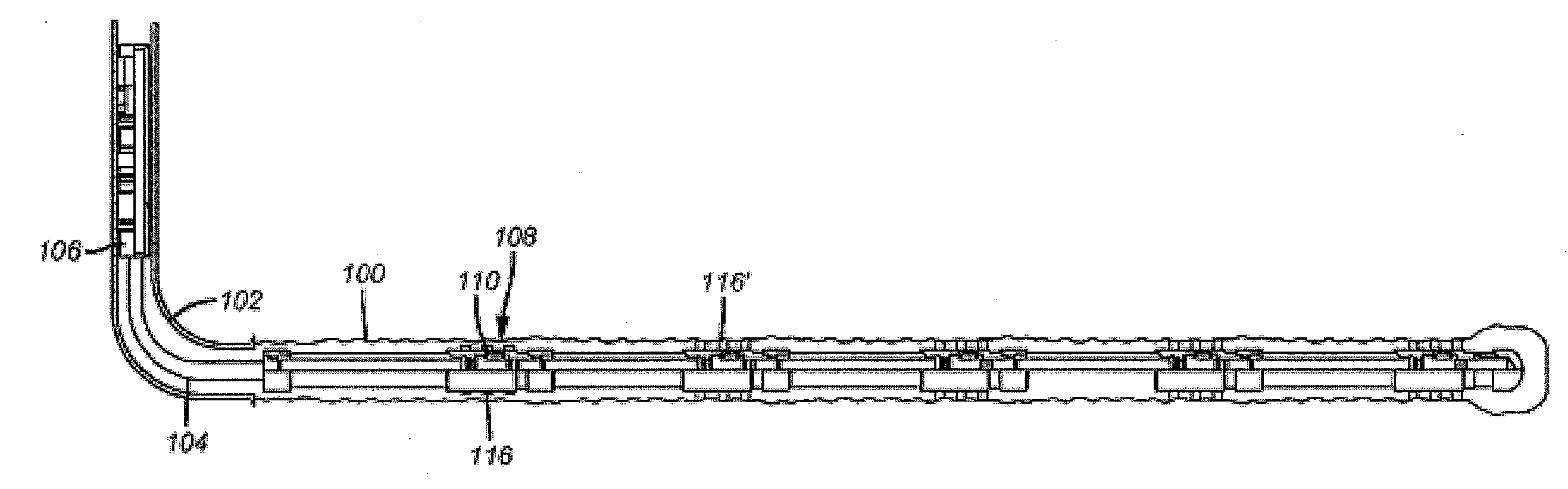
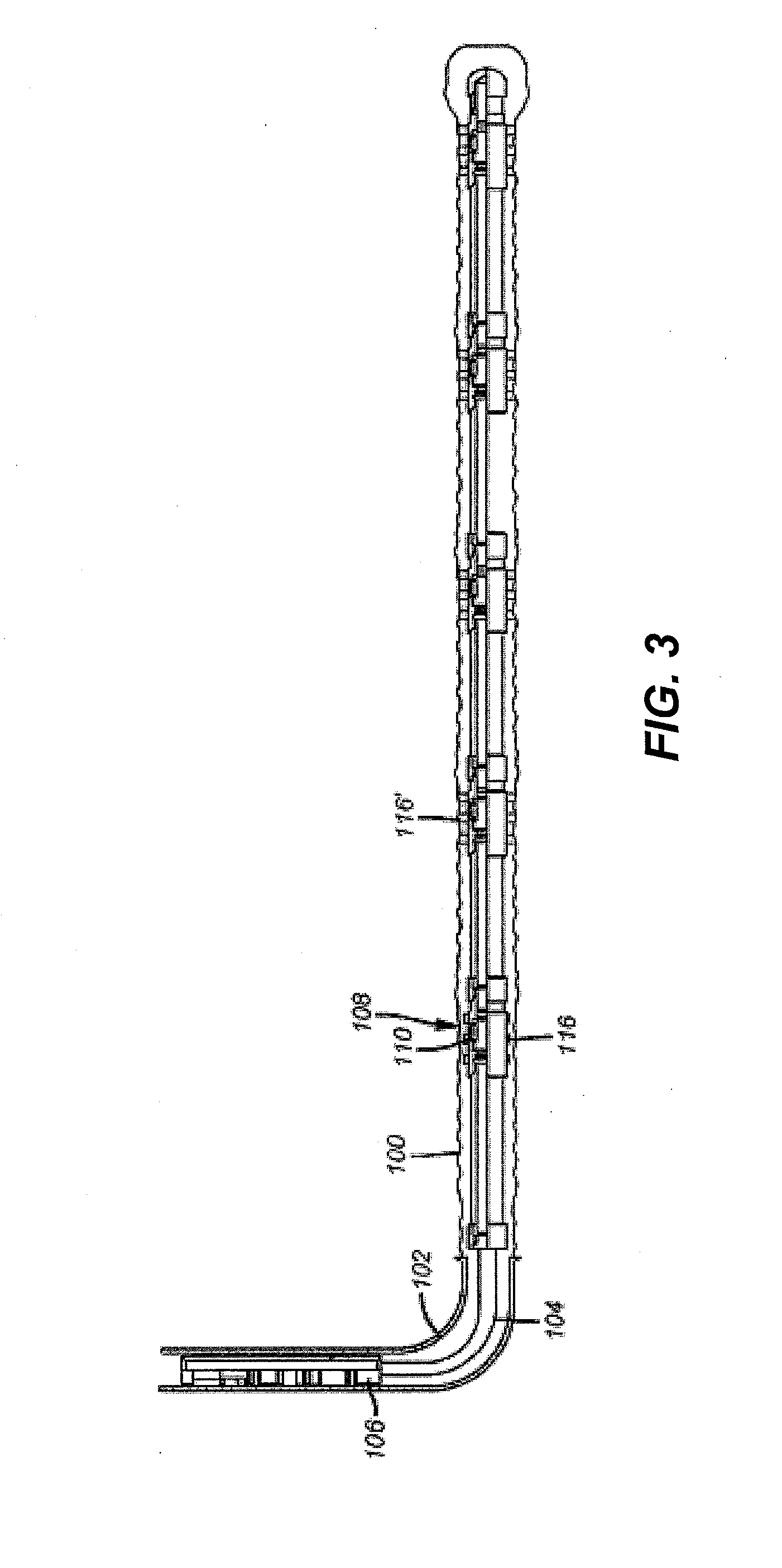
[0023]FIG. 3 illustrates an open hole 100 below a casing 102. A liner 104 is hung off casing 102 using a liner hanger 106. A fracturing assembly 108 is typical of the others illustrated in the FIG. 3 and those skilled in the art will appreciate that any number of assemblies 108 can be used which are for the most part similar but can be varied to accommodate actuation in a desired sequence as will be explained below. As shown in FIG. 4 each assembly 108 has a closure device that is preferably a sliding sleeve 110 that can be optionally operable with a ball 114 landing on a seat 112. In one embodiment, the seats and balls that land on them are all different sizes and the sleeves can be closed in a bottom up sequence by first landing smaller balls on smaller seats that are on the lower assemblies 108 and progressively dropping larger balls that will land on different seats to close the valve 110.

[0024]The array of extendable members 116 can comprise telescoping components, such as tele...


PUM


Abstract

A fracturing operation is done in open hole without annular space isolation. The annular space is spanned by extendable members that are located behind isolation valves. The extendable members can comprise a biodegradable plug that allows extension of the extendable members by application of pressure. With the plug remained in place, additional pressure can be delivered until at least a portion of the degradable material is pushed onto the surface of the formation. At least a portion of the pushed degradable material provides a seal between the end of the extendable members and the surface of the formation to allow pressure to build until the formation frac gradient is exceeded and the formation is fraced.

Description

PRIORITY INFORMATION[0001]This application claims priority to, and is a continuation-in-part application of, U.S. application Ser. No. 12 / 425,983, filed on Apr. 17, 2009, the disclosure of which is incorporated herein by reference.FIELD OF THE INVENTION[0002]The present invention relates to a system and method for fracturing an underground formation in an oil or gas well.BACKGROUND OF THE INVENTION[0003]There are two commonly used techniques to fracture in a completion method. FIG. 1 shows a borehole 10 that has a casing string 12 that is cemented 14 in the surrounding annulus 16. This is normally done through a cementing shoe (not shown) at the lower end of the casing string 12. In many cases if further drilling is contemplated, the shoe is milled out and further drilling progresses. After the string 12 is cemented and the cement 14 sets a perforating gun (not shown) is run in and fired to make perforations 18 that are then fractured with fluid delivered from the surface followed b...

Claims


Application Information

Patent Timeline
IPC IPC(8): E21B43/26
CPCE21B33/10E21B43/26E21B34/14E21B43/27
Inventor RICHARD, BENNETT M.XU, YANG
Owner RICHARD BENNETT M
Why Eureka
Try Eureka