Flume for a filter system including at least one filter having a filter bed that is periodically washed with liquid, gas or a combination thereof

a filter system and filter bed technology, applied in the direction of moving filter element filters, filtration separation, separation processes, etc., can solve the problems of high risk of mal-distribution of washing fluid through the filter bed, high risk of mal-distribution of washing fluid to the underdrain and ultimately the filter bed, etc., to reduce turbulence and disruption

Inactive Publication Date: 2010-07-20
RG DELAWARE
View PDF3 Cites 0 Cited by
  • Summary
  • Abstract
  • Description
  • Claims
  • Application Information

AI Technical Summary

Benefits of technology

[0011]Another object of a preferred embodiment of the present invention is to provide a filter system having a flume that can readily accommodate different washing procedures including but not limited to: (i) liquid only wash; (ii) air only wash; (iii) liquid and air concurrently; (iv) liquid only followed by air only; (v) air only followed by liquid only; and, (vi) liquid and air concurrently followed by liquid only.
[0012]A further object of a preferred embodiment of the present invention is to provide a flume that eliminates or significantly reduces the costly and arduous procedures of preforming orifices in baffles or stand-pipes located in the flume.
[0013]Yet another object of a preferred embodiment of the present invention is to provide a flume that optimizes flow distribution in the flume while mitigating flow disturbances including but not limited to velocity head, jet effect and turbulence.
[0014]Still another object of a preferred embodiment of the present invention is to provide a flume that is easy to construct and that more accurately controls the height of the gas / liquid interface over a wider range of flow conditions.
[0016]Still yet a further object of the present invention is to provide a flume that allows for a more controlled transition between low and high liquid flow rates.
[0023]Still yet a further embodiment of the present invention is to directed to a flume for a filter system including at least one filter having a filter bed that is periodically washed with liquid, gas and / or a combination of liquid and gas. The flume includes a chamber having a top wall, a bottom wall, a left sidewall and a right sidewall. The chamber is adapted to receive a liquid, a gas and / or a combination of liquid and gas. The flume also includes at least a first inner wall and an opening for creating a first liquid / gas interface upstream of the at least a first inner wall and a second gas / liquid interface downstream of the at least a first inner wall when gas and liquid are present in the chamber. The second liquid / gas interface is disposed below the first liquid / gas interface. The flume further includes a flow control member operably associated with the opening for diverting the flow of liquid passing through the opening to reduce turbulence and disruption of the second liquid / gas interface. The flow control member is disposed downstream of the opening and between the top wall, the bottom wall, the left sidewall and the right sidewall.

Problems solved by technology

One significant problem encountered by prior art devices is their inability to accommodate changes in the washing procedure including changes in the flow rates and changes in the washing fluids.
For example, a washing procedure that employs simultaneous liquid and air washing fluids is highly susceptible to mal-distribution of the washing fluid through the filter bed.
This is undesirable as it limits the area available for the washing liquid resulting in relatively high liquid washing flow velocities down the length of the flume which in turn causes mal-distribution of the washing fluids to the underdrain and ultimately the filter bed.
Forming orifices of the type illustrated in FIG. 1 of the subject specification normally requires expensive formwork to accommodate the air and water wall sleeves that are cast in place.
To be cost effective, the wall sleeves are made using commercially available sizes, which limits the available orifice sizes.
Hence, most designs are not optimal but rather less efficient designs due to the compromise between technical considerations and commercially available materials.
The orifice design disclosed and claimed in U.S. Pat. No. 6,312,611 is also inferior due to its inability to tailor the headloss characteristics over a range of flows.
This is particularly troublesome when the washing procedure includes a first step of concurrent liquid and gas followed by liquid only.
The increase in the flow rate of the washing fluid in the second step dramatically impacts the headloss across the orifice.
This dramatic increase in headloss creates very difficult flow control issues.
Poor flow control will likely result in disruption of the gas / liquid interface within the flume, mal-distribution of the washing fluids, and the undesirable release of uncontrolled air into the underdrain.
These conditions will likely cause structural failures of the underdrain system, disruption of the support gravel, and poor performance.
As is readily evident from the above discussion, the orifice design is inflexible from the design stand-point and the application stand point as the design is limited to commercially available sizes and is unable to accommodate changes in the washing procedure.

Method used


Image

  • Flume for a filter system including at least one filter having a filter bed that is periodically washed with liquid, gas or a combination thereof
  • Flume for a filter system including at least one filter having a filter bed that is periodically washed with liquid, gas or a combination thereof
  • Flume for a filter system including at least one filter having a filter bed that is periodically washed with liquid, gas or a combination thereof

Examples


Embodiment Construction

[0042]The preferred forms of the invention will now be described with reference to FIGS. 2-18. The appended claims are not limited to the preferred forms and no term and / or phrase used herein is to be given a meaning other than its ordinary meaning unless it is expressly stated otherwise. The term “orifice” as used herein and in the relevant industry means “an opening having a closed perimeter through which a fluid may discharge.”

FIGS. 2 Through 18

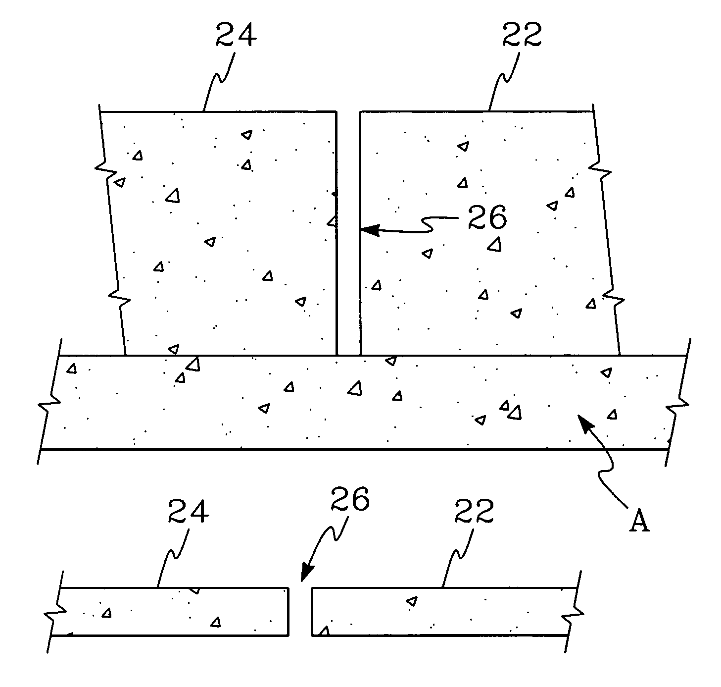
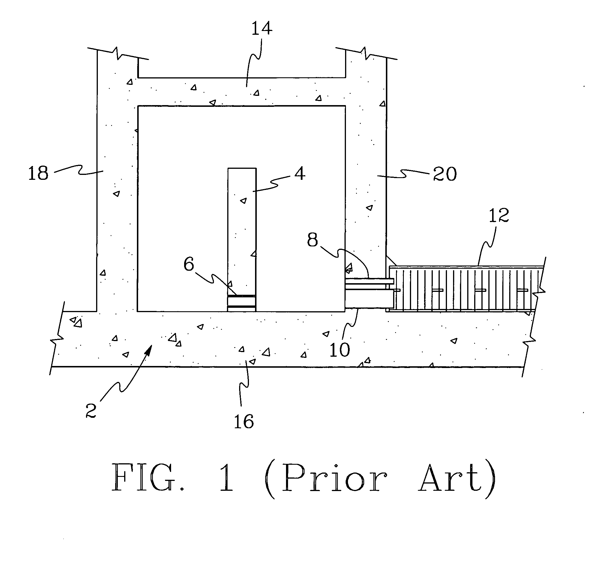
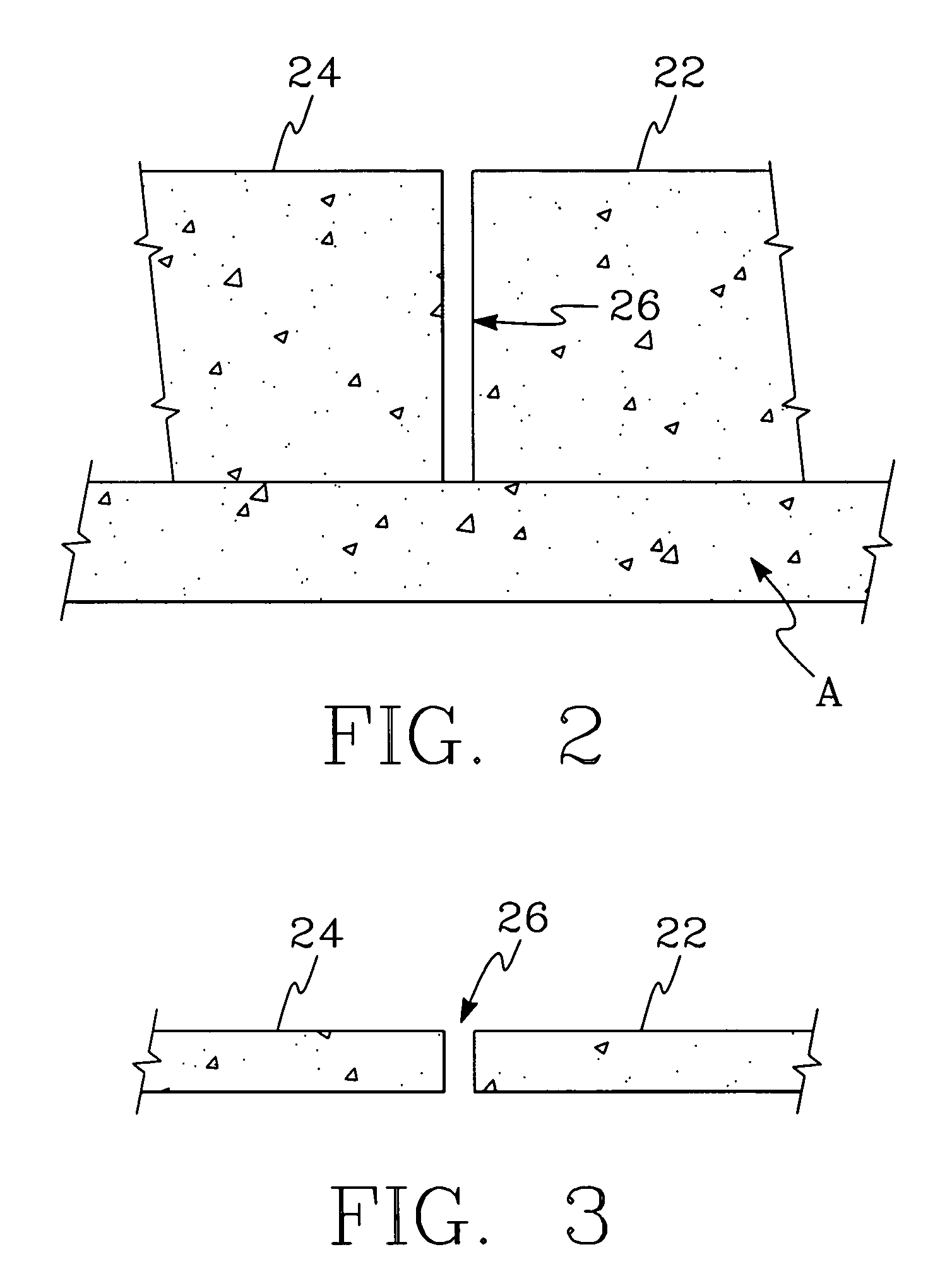
[0043]Referring to FIG. 2, a fragmentary portion of a flume A formed in accordance with a preferred embodiment of the present invention is illustrated. Preferably, flume A is similar in exterior construction to flume 2 depicted in FIG. 1, i.e., the flume A preferably has an exterior performed by a top wall 14, a bottom wall 16, a left sidewall 18 and a right sidewall 20 as depicted in FIG. 1. Preferably, the bottom wall is at approximately the same elevation as the bottom of the filter housing as shown in FIG. 1. This arrangement is often ...


PUM

PropertyMeasurementUnit
angleaaaaaaaaaa
distanceaaaaaaaaaa
heightaaaaaaaaaa

Abstract

A flume for a filter system including at least one filter having a filter bed that is periodically washed with liquid, gas and / or a combination of liquid and gas. The flume includes a chamber having a top wall, a bottom wall, a left sidewall and a right sidewall. The chamber is adapted to receive a liquid, a gas and / or a combination of liquid and gas. Preferably, the flumes includes at least a first inner wall and a second inner wall. Each of the first inner wall and the second inner wall are preferably free of any orifices. The first inner wall is positioned relative to the second inner wall such that an open space is formed between the first inner wall and the second inner wall. The open space creates a first liquid / gas interface upstream of the first inner wall and the second inner wall and a second gas / liquid interface downstream of the first inner wall and the second inner wall when gas and liquid are present in the chamber. The first interface is spaced from the bottom wall of the chamber a distance greater than the second interface.

Description

FIELD OF THE INVENTION[0001]The present invention is directed to a filter system having one or more filter beds that are periodically washed with a liquid, a gas and / or a combination of a liquid and a gas. Where a combination of a liquid and gas is used to wash the filter beds, the liquid and gas can be directed through the filter bed simultaneously or separately. More specifically, the present invention is directed to an improved flume used in a filter system having one or more filter beds that are periodically washed with a liquid, a gas and / or a combination of a liquid and a gas. The present invention can be used in both water and wastewater applications.BACKGROUND OF THE INVENTION[0002]Filter beds formed from one or more layers of filter media have been employed in a variety of known filters for filtering water or wastewater to remove impurities from liquids. For example, filter beds of granular media have been used in upflow filters, downflow filters as well as other type of fi...

Claims


Application Information

Patent Timeline
Patent Type & Authority Patents(United States)
IPC IPC(8): B01D24/46
CPCB01D24/22B01D24/4631
Inventor ROBERTS, R. LEEADDISON, MARK KEVIN
Owner RG DELAWARE
Why Eureka
Try Eureka