Automatic Torque Overload Clutch

a technology of torque overload and clutch, which is applied in the direction of clutches, freewheel clutches, slip couplings, etc., can solve the problems of inability to feed wood up to the maximum capacity of wood chippers, inability to effectively hammer the devices, and additional stresses that may negatively affect the operation life of devices, etc., to achieve the effect of enhancing consistent torque overload protection

Inactive Publication Date: 2012-03-29
WEASLER ENG
View PDF12 Cites 8 Cited by
  • Summary
  • Abstract
  • Description
  • Claims
  • Application Information

AI Technical Summary

Benefits of technology

[0008]The present invention generally provides a torque overload clutch having one or more improvements that enhance consistent torque overload protection.

Problems solved by technology

For instance, if the clutch decouples at a torque that is too low, the overall configuration may decouple prematurely thereby hampering effective operation of the devices.
Alternatively, if the clutch decouples at a torque that is too high, the additional stresses may negatively impact the operational life of the devices.
If the clutch decouples at too low of a torque value, the roller will not be able to feed wood up to the maximum capacity of the wood chipper.
Conversely, if the clutch decouples at too high of a torque value, the motor (and any intermediate gearing) is subjected to excess, undesirable stress.

Method used


Image

  • Automatic Torque Overload Clutch
  • Automatic Torque Overload Clutch
  • Automatic Torque Overload Clutch

Examples


Embodiment Construction

[0021]An example embodiment of a torque overload clutch will be described; however, as one skilled in the art will appreciate, the concepts described are applicable to various applications and subject to numerous modifications that fall within the scope of the claims.

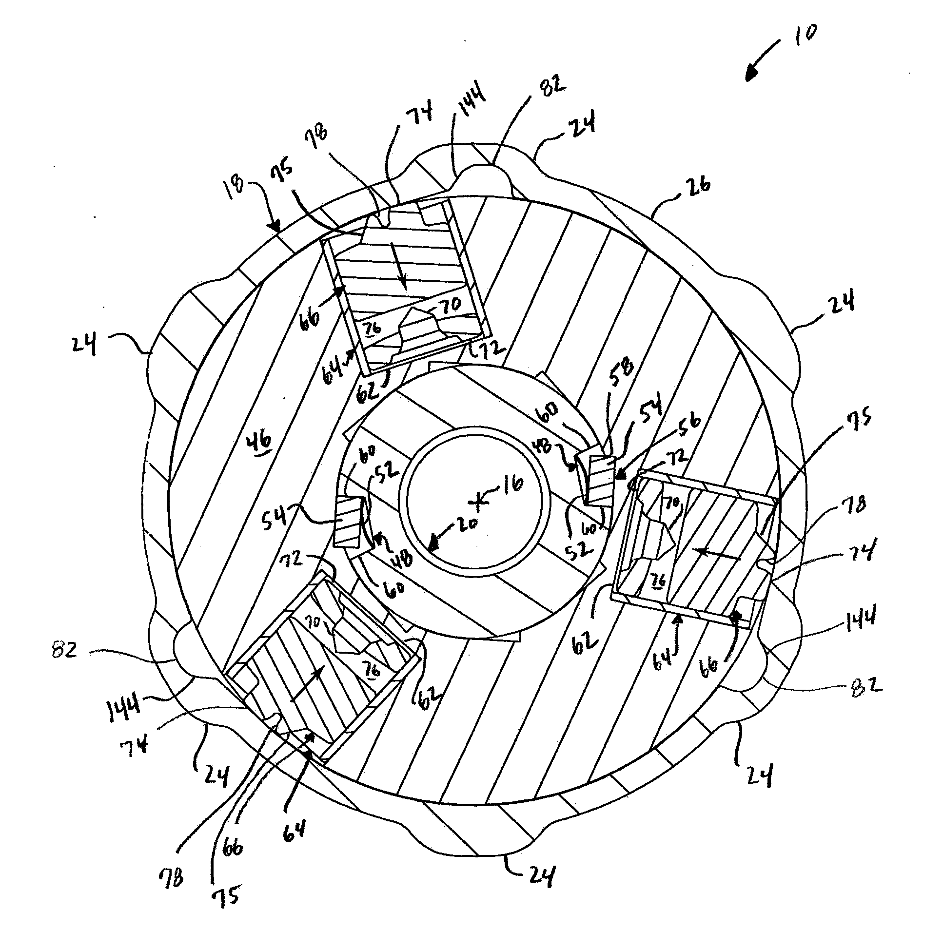
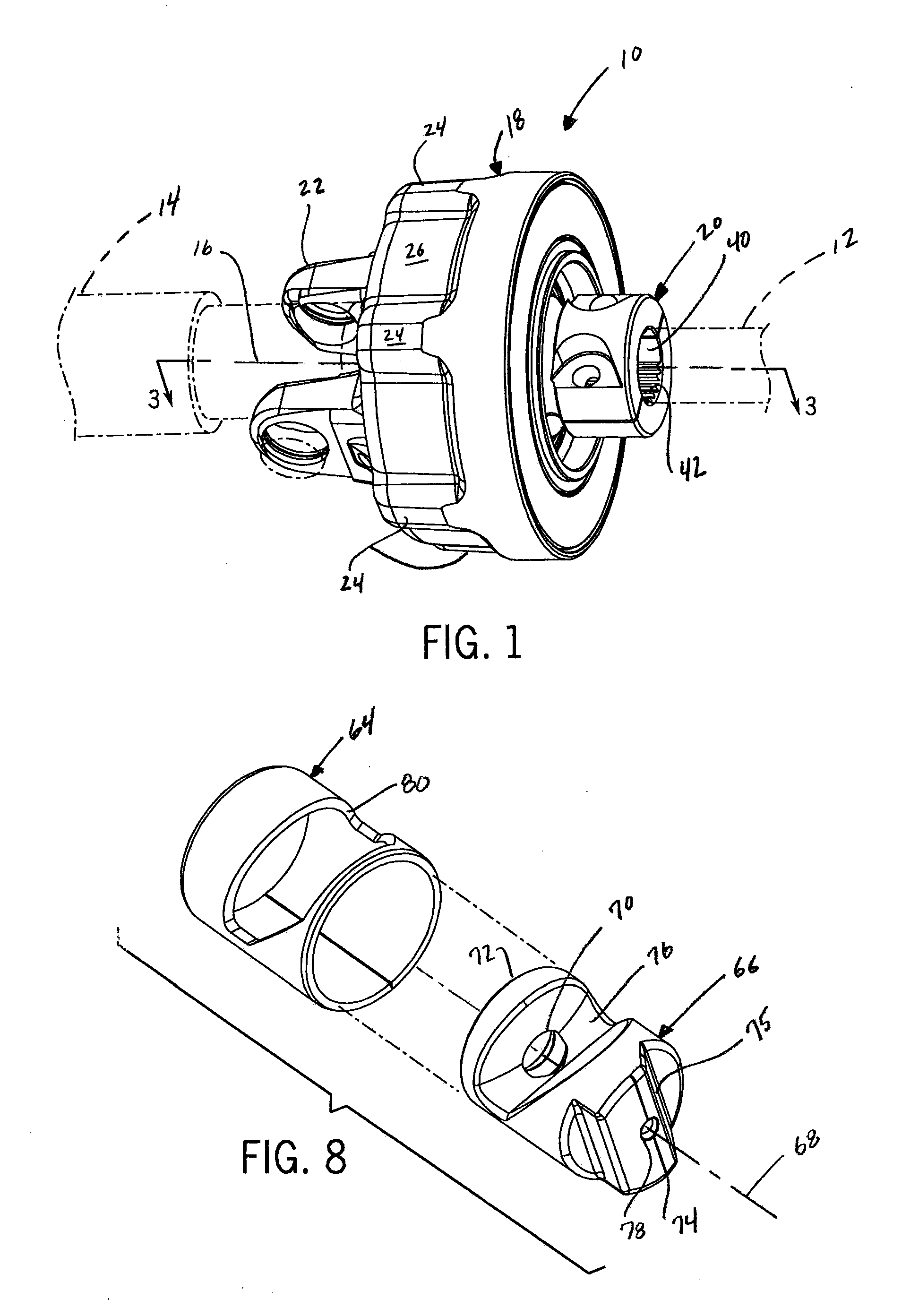
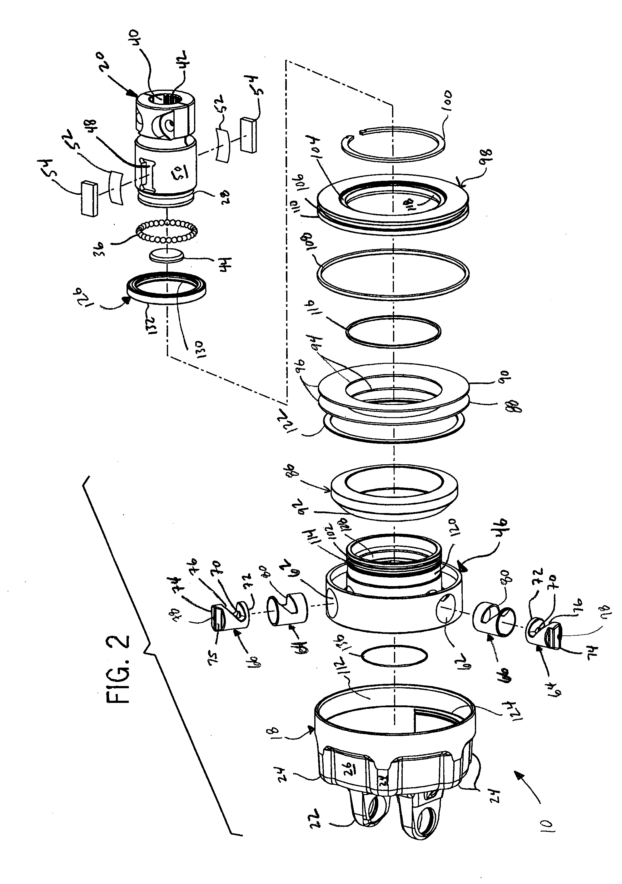
[0022]An example torque overload clutch (10), in the form of an automatic torque overload clutch, is illustrated in FIG. 1 and referred to herein as the “clutch (10).” The clutch (10) is configured to transfer torque between devices, such as a drive member (12) and a driven member (14). As one skilled in the art will understand, the devices can be any number of machine components that benefit from consistent torque overload protection. In the example embodiment, the clutch (10) transfers torque between the drive member (12) and the driven member (14) in one direction of rotation about a clutch axis (16) up to a pre-set value. If the torque exceeds the pre-set value, the clutch (10) decouples the drive member (12) and th...


PUM


Abstract

A torque overload clutch, in one form, comprises outer and inner members. A recess is formed in the outer member and a radial opening is formed in the inner member. A driving member is slideably captured in the opening to move between an extended, engaged position with the recess and a retracted, disengaged position. An actuator ring is urged by a spring into engagement with the driving member to bias the driving member toward the engaged position. An end of the driving member may engage the recess to define an engagement angle that is approximately between thirty-four degrees and seventy-degrees relative to a radially oriented reference. The driving member may be slideably captured in a liner seated in the opening, and one or both may be impregnated with a lubricant. A bearing may be positioned between the inner and outer members to inhibit relative movement there between along the clutch axis.

Description

CROSS REFERENCES TO RELATED APPLICATIONS[0001]This application claims priority to U.S. Provisional Application No. 61 / 387,748 filed on Sep. 29, 2010, which is hereby incorporated by reference as if fully set forth herein.STATEMENT REGARDING FEDERALLY SPONSORED RESEARCH[0002]Not applicable.BACKGROUND OF THE INVENTION[0003]The present invention relates to torque overload clutches, and more particularly to automatic torque overload clutches providing consistent torque overload protection.[0004]Torque overload clutches are used in various applications to generally limit the maximum level of torque transferred between two or more devices that are coupled to the clutch, such as a drive shaft and a driven shaft. When the amount of torque being transferred through the clutch exceeds a set level, the clutch allows for relative rotation between the devices to minimize any undesirable consequences associated with excess torque transfer. Some torque overload clutches provide for automatic re-co...

Claims


Application Information

Patent Timeline
Patent Type & Authority Applications(United States)
IPC IPC(8): F16D7/04F16D41/18
CPCF16D7/048
Inventor JAEGER, DARYL J.
Owner WEASLER ENG
Why Eureka
Try Eureka