Wind turbine with feed line

a technology of wind turbines and feed lines, which is applied in the direction of electric generator control, machines/engines, mechanical equipment, etc., can solve the problems of high currents of circuit breakers on the low-voltage side of turbine transformers, impracticality, and expensive special designs for circuit breakers, so as to increase the impedance of transformers and reduce the cost of configuration

Active Publication Date: 2018-10-04
SIEMENS GAMESA RENEWABLE ENERGY SERVICE GMBH
View PDF10 Cites 5 Cited by
  • Summary
  • Abstract
  • Description
  • Claims
  • Application Information

AI Technical Summary

Benefits of technology

[0010]Preferably, the low-voltage windings of the first or second feed line (or additional feed lines) act on a common medium-voltage winding of the turbine transformer. Thus, a multiple-winding transformer is provided in which multiple low-voltage windings act on a common medium-voltage winding. This enables a compact and cost-saving configuration. Nonetheless, the self-sufficiency of the individual feed lines underlying the present invention, in which exactly one low-voltage winding of the transformer is associated with each power circuit breaker, is fully maintained.
[0011]Alternatively, however, it may also be provided that separate turbine transformers are provided for the feed lines, so that each feed line has its own transformer. Although this is more complex, it may provide the advantage of higher redundancy. Furthermore, this has the particularly significant advantage within the scope of the present invention that an increase in impedance of the transformers thus results, so that the short-circuit current in the respective feed line is decreased. Thus, additional relief is provided to the power circuit breakers.
[0012]It is particularly preferred if there is no cross-connection between the first and the second feed lines (and possibly additional feed lines). It is thus achieved that even in the case, for example, of a defective power circuit breaker, no current is able to flow out of the one feed line through the power circuit breaker of the other feed line. The desired overload protection is thus increased.
[0013]Furthermore, it may advantageously be provided that two (or more) converters are provided, to which the two (or more) feed lines are connected. Since a separate converter may thus be associated with each feed line, the described effect also holds true with respect to the converter. Thus, even in normal operation, in the case of a malfunction of a power circuit, it cannot occur that the adjacent power circuit breaker would have to accommodate correspondingly more current, and would thereby be overloaded. Thus, the reliability is further increased.
[0014]Advantageously, the transformers associated with the feed lines are sized equally, wherein sizing deviations are allowable up to a maximum deviation of 20%, preferably a maximum of 10%. By means of this equal sizing, it is achieved that in the normal case, the feed lines are all equally loaded. It is thus avoided that certain power circuit breakers are loaded with larger currents than another of the power circuit breakers, so that the wear of the power circuit breakers, which is unavoidable per se, is also evened out. Thus, not only is the fail-safety improved, but also the operational reliability of the wind turbines overall.

Problems solved by technology

In this case, it is problematic that the circuit breakers on the low-voltage side of the turbine transformer have quite high currents.
In the case of the wind turbine power levels of several megawatts which are now being achieved, this sometimes makes expensive special designs necessary for the circuit breakers.
However, this has proven to be impractical due to the upper limits for voltages which are defined in relevant standards; thus, they still fall into the low-voltage range.
However, this has proven to be insufficiently operationally reliable in the case of switchover.
Due to structural tolerances, it is practically unavoidable that one of the two circuit breakers switches faster than the other; thus, in the interim, the entire current flows via only a single circuit breaker.
This circuit breaker thereby becomes overloaded.
This problem has a particularly unfavorable effect in the case of a short circuit, if the highest current load occurs.
As a result, this means that precisely in the situation when the circuit breakers are needed (for example, in a short circuit), there is a high probability that they will fail due to overloading.
This is unsatisfactory.

Method used


Image

  • Wind turbine with feed line
  • Wind turbine with feed line
  • Wind turbine with feed line

Examples


Embodiment Construction

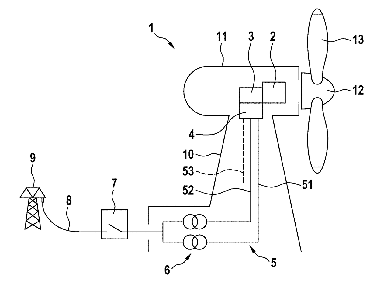
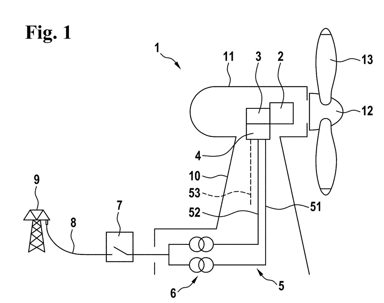
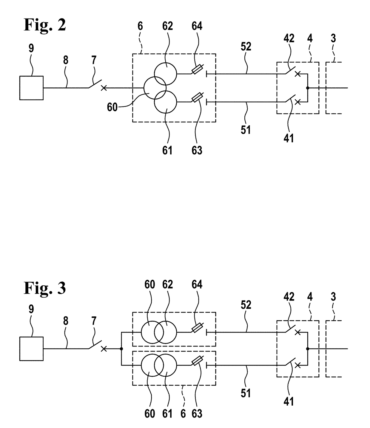
[0022]A wind turbine according to one exemplary embodiment of the present invention, which is referred to in its entirety by the reference numeral 1, comprises a nacelle 11 which is pivotably arranged on the upper end of a tower, on the front side of which a wind rotor 12 having multiple rotor blades 13 is rotatably arranged. Via a rotor shaft (not depicted), the wind rotor 12 drives a generator 2 which converts the mechanical power supplied by the wind rotor 12 into electric power and outputs it via a converter 3. At the output of the converter 3, a power circuit breaker unit 4 is arranged which, in the depicted exemplary embodiment, comprises a first power circuit breaker 41 and a second power circuit breaker 42. From there, the electric power is supplied at a low-voltage level via feed lines 5 to a turbine transformer 6. The turbine transformer 6 is designed to raise the electric power supplied at the low-voltage level to a medium-voltage level and to output it via a medium-volta...


PUM


Abstract

A wind turbine includes a wind rotor, a generator, and a converter. The generated electric power is fed from the converter by means of a feed to a turbine transformer for delivery to a grid. The feed is designed as a double branch including a power-branched power circuit breaker unit having a first feed line and a second feed line connected in parallel, wherein a separate low-voltage winding of the turbine transformer and a separate power circuit breaker at the connector of the converter is associated with each feed line.

Description

CROSS-REFERENCE TO RELATED APPLICATIONS[0001]This application claims the priority of German Application No. 10 2017 003 078.2, filed Mar. 30, 2017, the entire contents of which are incorporated herein by reference.FIELD OF THE INVENTION[0002]The present invention relates to a wind turbine comprising a wind rotor, a generator, and a converter, for generating electric power which is delivered to a grid via a turbine transformer.BACKGROUND OF THE INVENTION[0003]Modern wind turbines are capable of generating a considerable amount of electric power. They typically have power ratings of several megawatts. The electric power generated by the wind turbine is generally raised to a higher voltage level (usually a medium-voltage level) which is more suitable for transmission, via a transformer which is associated with the wind turbine (turbine transformer). For protecting the wind turbines and the grid, circuit breakers are required on both sides of the turbine transformer. In this case, it is...

Claims


Application Information

Patent Timeline
Patent Type & Authority Applications(United States)
IPC IPC(8): H02H7/06H02P9/10F03D9/25
CPCH02H7/06H02P9/107F03D9/255H02P2101/15F05B2220/706H02J3/005H02J2300/28H02J3/381F03D80/85Y02E10/76Y02E10/72H02J3/38
Inventor LETAS, HEINZ-HERMANN
Owner SIEMENS GAMESA RENEWABLE ENERGY SERVICE GMBH
Why Eureka
Try Eureka