Micromechanical sensor system, method for using a micromechanical sensor system

a micromechanical sensor and sensor technology, applied in the direction of speed/acceleration/shock measurement, flexible microstructural devices, instruments, etc., can solve the problems of reducing the restoring force of springs, increasing the risk of adhesion (stiction), and ultimately showing an increased tendency of sensors to adhesion, so as to increase the overload protection and reduce the risk of adhesion

Active Publication Date: 2021-11-04
ROBERT BOSCH GMBH
View PDF0 Cites 4 Cited by
  • Summary
  • Abstract
  • Description
  • Claims
  • Application Information

AI Technical Summary

Benefits of technology

[0011]It is an object of the present invention to provide a micromechanical sensor system which has an increased overload protection, it being possible, in particular, to reduce an adhesion risk in a robust and efficient manner.

Problems solved by technology

However, this also results in a decrease of the spring restoring forces when the sensor bounces against a stop.
Both trends in combination, increasing shock loads, while simultaneously striving for miniaturization, result in a considerably increased risk of adhesion (stiction), in which the movable sensor mass remains adhered to a mechanical fixed stop as soon as the adhesion forces in the stop are greater than the restoring forces of the spring-mass system.
However, if a sensor strikes against a stop very often, the ASC may become damaged, so that the sensor ultimately shows an increased tendency toward adhesion.
Even though resilient stops, with appropriate dimensioning, contribute to an effective increase in the restoring force, adhesion remains a considerable challenge for the quality of sensors and, in particular, also of z acceleration sensors.

Method used


Image

  • Micromechanical sensor system, method for using a micromechanical sensor system
  • Micromechanical sensor system, method for using a micromechanical sensor system
  • Micromechanical sensor system, method for using a micromechanical sensor system

Examples


Embodiment Construction

[0040]Identical parts are denoted by the same reference numerals in the various figures and are therefore generally also cited or mentioned only once.

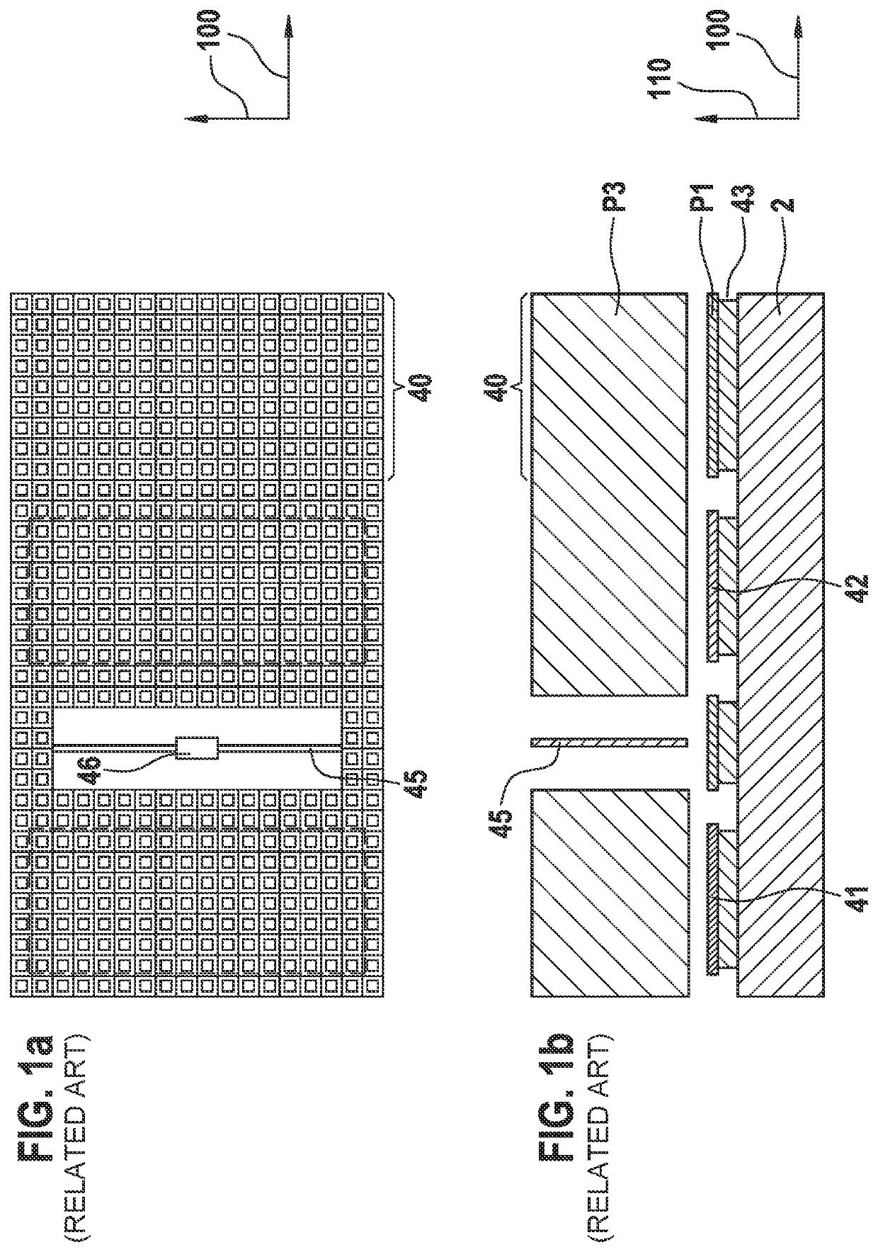
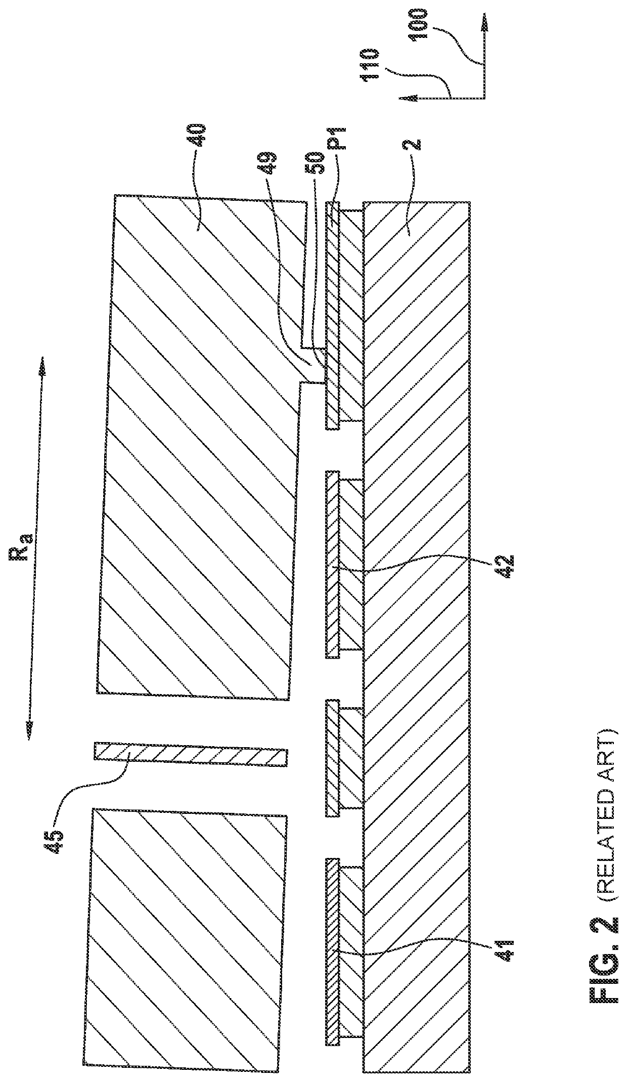
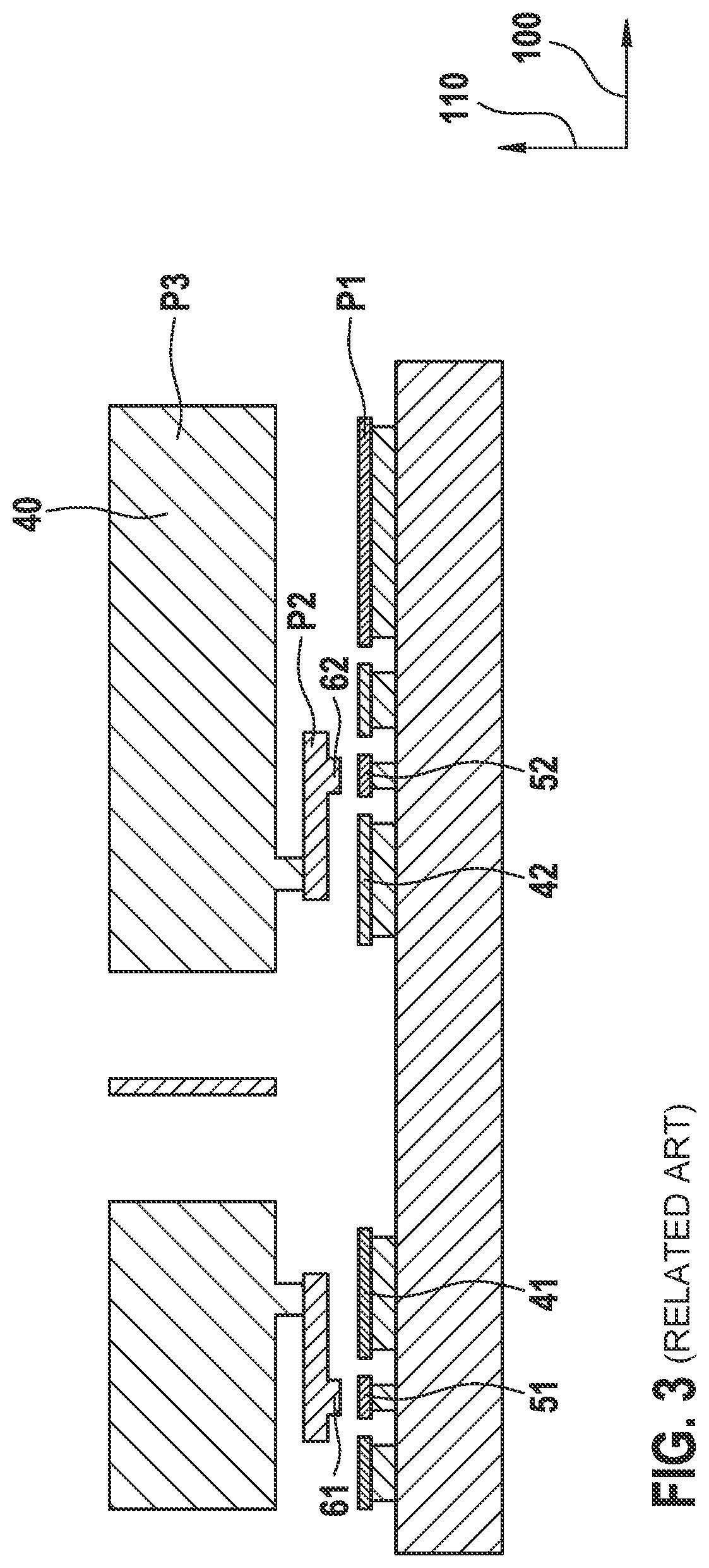
[0041]FIGS. 1a and 1b show a system of a capacitive acceleration sensor having a detection direction in a vertical direction 110 (z direction), perpendicular to main extension plane 100 of substrate 2, according to the related art. The sensor according to FIGS. 1a and 1b is designed as a “rocker structure” or “rocker.” The sensor principle of these rockers is based on a spring-mass system in which, in the simplest case, a movable asymmetrical seismic mass 40, which is implemented in functional layer P3 in FIGS. 1a and 1b, together with two evaluation electrodes 41, 42 which are fixed on the substrate at a distance d0 and implemented in layer P1, forms two plate capacitors having capacitances C1 and C2. Seismic mass 40 is connected to the base or substrate 2 via at least one torsion spring 45 (for symmetry reasons, usually rather two to...


PUM


Abstract

A micromechanical sensor system, in particular, an acceleration sensor, including a substrate having a main extension plane, the sensor system including a first mass and a second mass. The first and second masses are each designed to be at least partially movable in a vertical direction, perpendicular to the main extension plane of the substrate. The first mass includes a stop structure, wherein the stop structure has an overlap with the second mass in the vertical direction.

Description

CROSS REFERENCE[0001]The present application claims the benefit under 35 U.S.C. § 119 of German Patent Application No. DE 102020205616.1 filed on May 4, 2020, which is expressly incorporated herein by reference in its entirety.BACKGROUND INFORMATION[0002]The present invention is directed to a micromechanical sensor system.[0003]Such micromechanical sensor systems or microelectromechanical systems (MEMS) are generally conventional. They are manufactured in mass production, for example, for measuring accelerations and / or rotation rates for different applications in the automobile and consumer areas.[0004]For example, so-called “rockers” or rocker structures are utilized as capacitive acceleration sensors with a detection direction perpendicular to the wafer plane (typically referred to as the z direction). The sensor principle of these rockers is based on a spring-mass system in which, in the simplest case, a movable asymmetrical seismic mass, together with two counter electrodes, for...

Claims


Application Information

Patent Timeline
Patent Type & Authority Applications(United States)
IPC IPC(8): G01P15/08
CPCG01P15/0802G01P15/18G01P15/125B81B7/02B81B2201/0235G01P2015/0831G01P2015/0871B81B3/0051B81B2201/025B81B2203/0181
Inventor CLASSEN, JOHANNES
Owner ROBERT BOSCH GMBH
Why Eureka
Try Eureka