
Robot power source charging station

a charging station and power source technology, applied in the field of robot power source charging stations, can solve the problems of significant drawbacks or deficiencies of charging arrangements of this type, when used outdoors, degraded or diminished the ability to transfer power to the robot, use of conductive elements, and oxidation and mechanical fatigu

Active Publication Date: 2012-03-29
DEERE & CO
View PDF6 Cites 262 Cited by
  • Summary
  • Abstract
  • Description
  • Claims
  • Application Information

AI Technical Summary

Problems solved by technology

However, charging arrangements of this type, when used outdoors, can have significant drawbacks or deficiencies.
However, these conductive elements are typically exposed to weather conditions and moisture, and over time may become oxidized and mechanically fatigued.
As a result, the capability to transfer power to the robot, using these conductive elements, becomes degraded or diminished, and the overall system durability, compromised.
Another problem with presently used outdoor charging systems is that an exterior or outdoor electric outlet will generally be required as a power source, but may not be conveniently available.
In either case, it would be necessary to install an exterior outlet, which could be expensive and also destructive to the building.
In addition, outdoor charging systems of the above type generally have only a single charging station.
This can result in excessive wear of grass or other yard elements that are adjacent to the station, since the robotic mower must frequently go to and maneuver around this location.
However, it would then be necessary to provide an exterior outlet at each of the multiple locations, which could further aggravate the problem discussed above in regard to the availability of such outlets, as well as increasing overall system cost.

Method used


Image

  • Robot power source charging station
  • Robot power source charging station
  • Robot power source charging station

Examples


Embodiment Construction

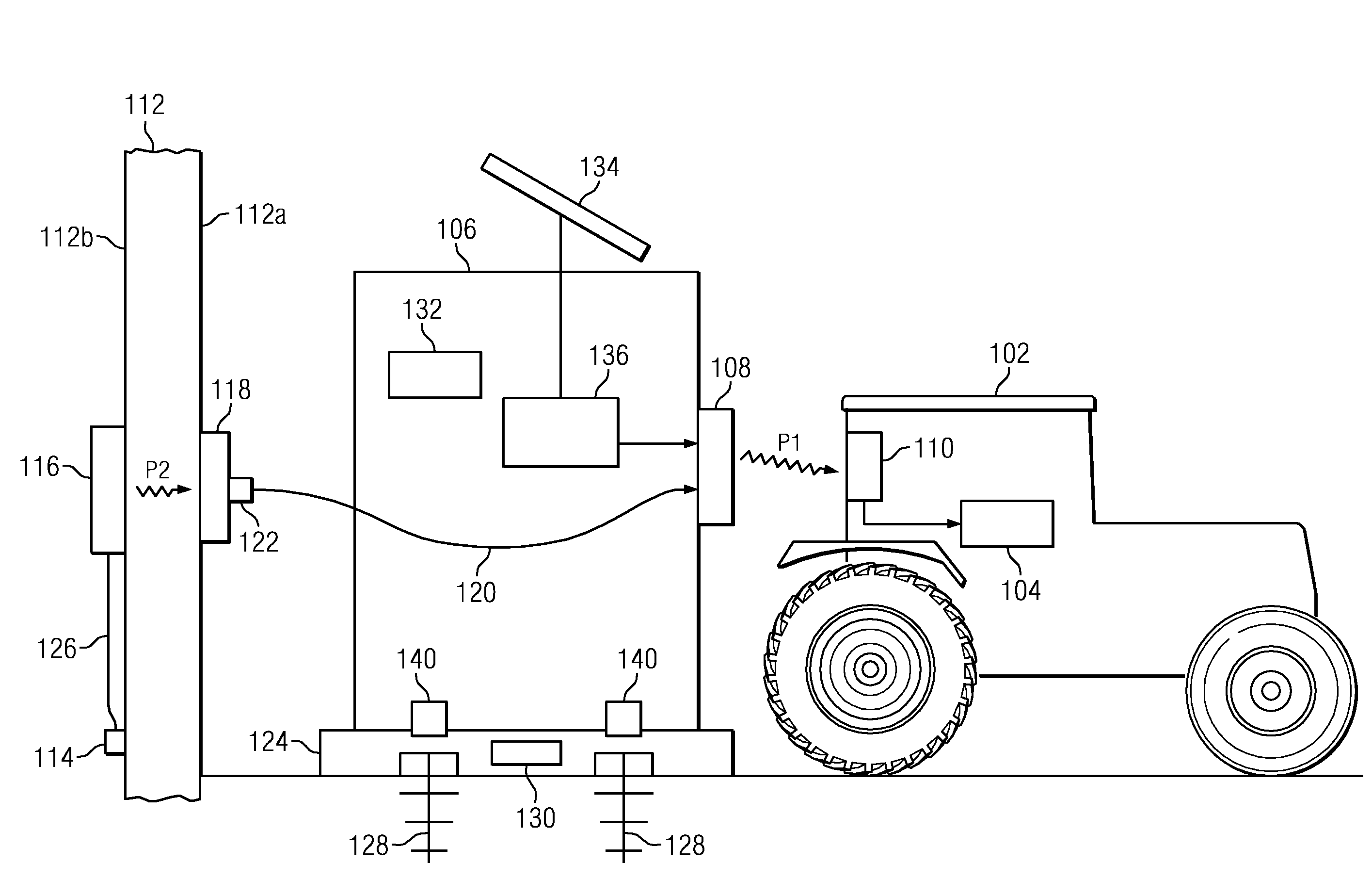
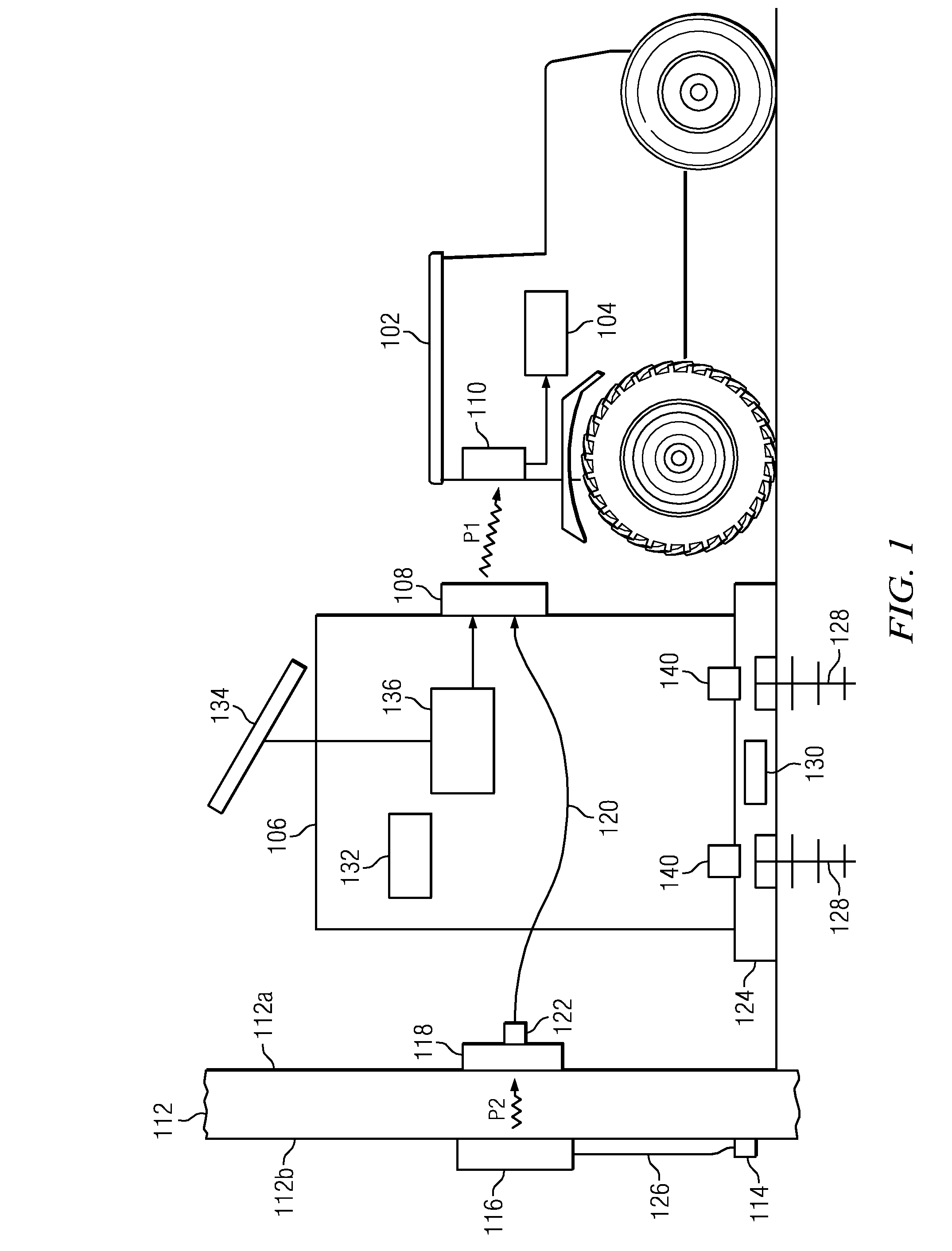
[0011]Referring to FIG. 1, there is shown a service robot 102 for performing outdoor tasks of some type, as directed by a conventional control mechanism (not shown) that may be remotely located or carried aboard the robot. Robot 102 may by way of example comprise a robotic lawnmower, but the invention is not limited thereto. FIG. 1 shows robot 102 provided with a rechargeable electric battery 104, which provides power for moving and maneuvering robot 102, and also for performing other functions needed in the operation of robot 102.

[0012]FIG. 1 further shows a charging station 106, which is provided to charge or recharge battery 104 of the service robot 102, as required. Station 106 is removably placed upon a plate or base plate 124, described hereinafter in further detail. In accordance with an embodiment of the invention, station 106 is furnished with a wireless power transmitter 108, which is coupled to a source of power as likewise described hereinafter in further detail. Robot 1...


PUM


Abstract

Embodiments of the invention are directed to a system for recharging a mobile robot as a power source. In one embodiment the system comprises a power transmission link having a first end positioned at a selectively located charging station and a second end connected to the battery carried by the robot, the transmission link being configured to transmit power from its first end to its second end to charge the battery. The system further comprises a first wireless power transmitter coupled to receive power from a specified power source, and a first wireless power receiver, connected to the first end of the transmission link and located at a prespecified distance from the first wireless power transmitter. The first wireless power receiver is configured to receive power transmitted across the prespecified distance from the first wireless power transmitter, and to provide power to the first end of the transmission link, for transmission to charge the battery.

Description

FIELD OF THE INVENTION[0001]The invention disclosed and claimed herein pertains to a system and method for charging a battery used as a power source for a mobile robot or the like. More particularly, the invention pertains to a system and method of the above type that uses wireless power transmission, thus delivers more mobile robot durability, and is minimally destructive to the surrounding environment.BACKGROUND OF THE INVENTION[0002]Power charging stations for mobile outdoor service robots, such as robotic lawnmowers, are well known in the art. If a robot vehicle uses an electric battery as a source of power, the robot can be directed to the station whenever it is necessary to charge or recharge the battery. However, charging arrangements of this type, when used outdoors, can have significant drawbacks or deficiencies.[0003]As an example, in currently available systems, both the robot vehicle and the charging station have corresponding or complementary conductors or conductive el...

Claims


Application Information

Patent Timeline
IPC IPC(8): H02J7/00
CPCB60L11/182H02J7/35Y02T10/7005Y02T10/7094Y02T90/122Y02T90/124Y02T90/14Y02T90/12B60L2230/22B60L2230/24B60L2230/28H02J7/0042H02J7/0055H02J7/025H02J7/34H02J7/345Y02B10/30B60L2200/40B60L2250/10B60L53/12B60L53/30B60L53/36B60L53/305B60L53/51B60L53/52B60L53/54B60L53/53B60L53/55H02J2207/40H02J50/10B60L53/67B60L53/68Y02T10/7072Y02T90/16Y02T10/70H02J50/90H02J50/60
Inventor ANDERSON, NOEL WAYNEFOESSEL, ALEX D.VALENTINE, ANDREW JOSEPH
Owner DEERE & CO
Learn More