
Power supply device

a power supply device and power supply technology, applied in the direction of circuit monitoring/indication, generator circuit arrangement control, transportation and packaging, etc., can solve the problems of inability sometimes unable to charge up, and sometimes unable to detect a negative voltage, etc., to achieve efficient charging up

Active Publication Date: 2012-03-29
MITSUBISHI ELECTRIC CORP
View PDF4 Cites 7 Cited by
  • Summary
  • Abstract
  • Description
  • Claims
  • Application Information

AI Technical Summary

Benefits of technology

The present invention is a power supply device that can efficiently charge a battery by changing three-phase AC voltages into stable ones without voltage imbalance between the phases. The device includes a rectification means for synchronously rectifying the three-phase AC voltages generated by a generator to produce a charging voltage for the battery. A switch control means controls each of semiconductor switches constituting the rectification means at intervals in response to the charging status of the battery. A negative voltage detection means detects a negative voltage at each of the three phases of the three-phase AC voltages, and a voltage detection means detects the battery voltage being higher than a predetermined voltage. When a negative voltage or the battery voltage is detected, the switch control means controls each of the semiconductor switches. An abnormality detection means monitors the status of the negative voltage at each phase and detects an abnormality in at least one of the three phases. When an abnormality is detected, the means through the switch control means controls the semiconductor switch corresponding to the phase of the abnormality. This prevents voltage imbalance between the three phase AC voltages output from the generator and ensures efficient charging of the battery.

Problems solved by technology

However, the voltage imbalance between the three phases that has arisen during the charge-stop state continues for several periods immediately after the state changing from the charge-stop to charge-permit state; therefore, in a phase that has been firstly short-circuited, a negative voltage sometimes cannot be detected for these several periods.
If the charging up starts without detecting the negative voltage, a phase in which the negative voltage cannot be detected cannot be short-circuited, and furthermore, the voltage at the phase in which the negative voltage cannot be detected stays high making it unable to detect a negative voltage because the charging up of the battery has already started.
The switch corresponding to the phase in which the negative voltage cannot be detected is continuously held conductive, thereby causing problems in that the semiconductor switch is broken down precluding the synchronous rectification, so that the battery 7 cannot be charged up.

Method used


Image

  • Power supply device
  • Power supply device
  • Power supply device

Examples


embodiment 1

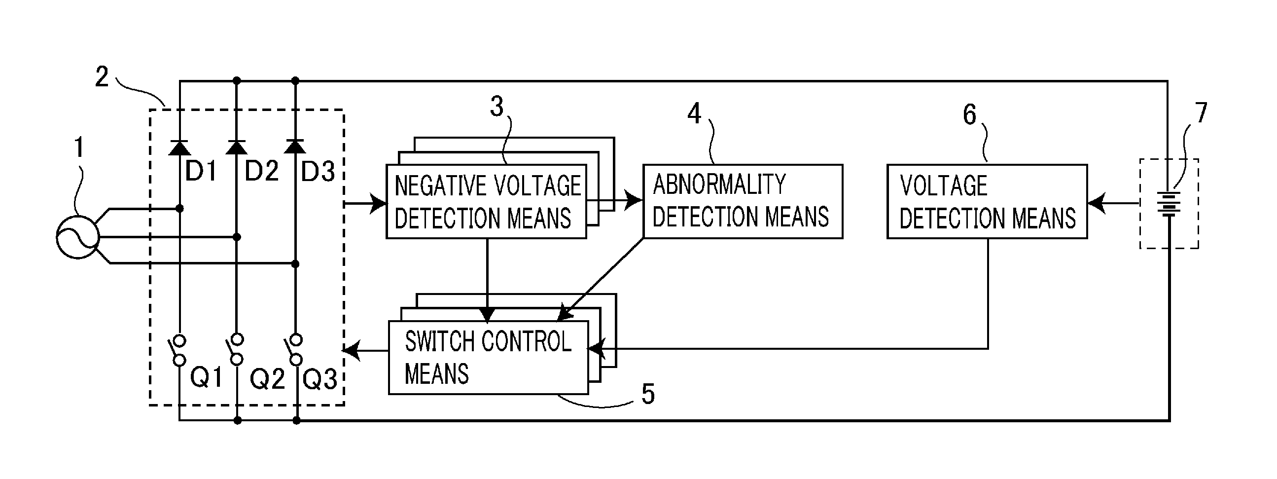
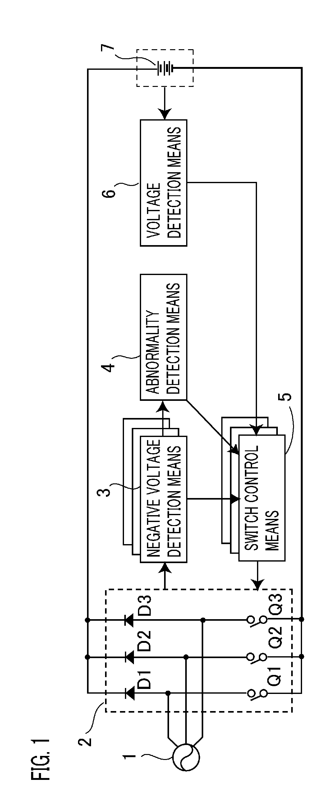
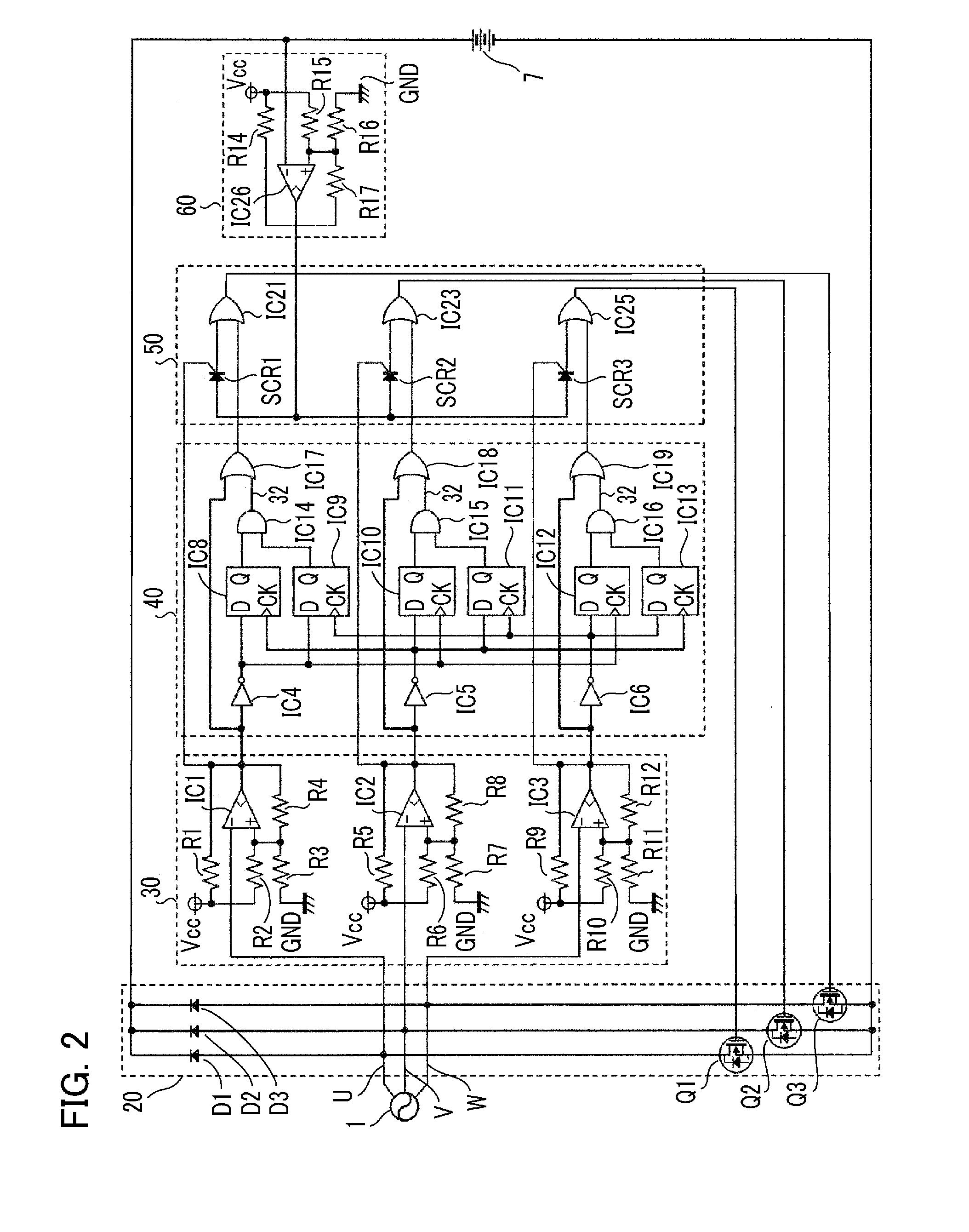
[0025]FIG. 1 is a block diagram showing the configuration of a power supply device according to Embodiment 1 of the present invention; FIG. 2 is a circuit diagram showing a specific configuration thereof.

[0026]A power supply device according to Embodiment 1 of the present invention includes a rectification means 2 for synchronously rectifying three-phase AC voltages generated by a generator 1 so as to produce a charging voltage for charging up a battery 7; a switch control means 5 for controlling each of semiconductor switches Q1 to Q3, constituting the rectification means 2, at intervals in response to the charging status of the battery 7; a negative voltage detection means 3 for detecting a negative voltage at each phase of the three-phase AC voltages; and a voltage detection means 6 for detecting the battery voltage being higher than a predetermined voltage, wherein the switch control means 5 controls each of the semiconductor switches Q1 to Q3 when the negative voltage or the ba...

embodiment 2

[0043]In Embodiment 2 of the present invention, another abnormality detection method is implemented in the power supply device shown in FIG. 1 according to Embodiment of the invention, in which sequence of detecting negative voltages at the three phases is monitored, and when an abnormality in the sequence of detecting the negative voltages is detected, the phase corresponding to the abnormality is determined to be in an abnormal state.

[0044]FIG. 4 to FIG. 7 show flowcharts for the negative voltage detection means 3, the abnormality detection means 4, the voltage detection means 6 and the switch control means 5 in FIG. 1, respectively.

[0045]As shown in FIG. 4, the negative voltage detection means 3 determines phase by phase whether or not each voltage from the generator 1 is lower than zero, and if so, then turns on the switch corresponding to the phase, whereas if not lower than zero, turns off the switch (Steps S31 to S40).

[0046]Moreover, the abnormality detection means 4, as show...

embodiment 3

[0051]In Embodiment 3 of the present invention, still another abnormality detection method is implemented in the power supply device shown in FIG. 1 according to Embodiment 1 of the invention, in which if a negative voltage fails to be detected at each of the three phases at a predetermined time, the phase corresponding to the failure is determined to be in an abnormal state, and controlling of the semiconductor switch corresponding to the phase is continued until a negative voltage is detected.

[0052]The operation of the abnormality detection means 4 will be explained referring to the flowchart in FIG. 8.

[0053]The abnormality detection means 4 detects a rising edge of an output voltage from each phase of the negative voltage detection means 3 (Steps S70 and S71). If a rising edge is detected, its counter is reset and then a predetermined value is preset in the counter (Step S74). When presetting the predetermined value in the counter, the value can be adjusted in accordance with the...


PUM


Abstract

A power supply device capable of switching over semiconductor switches of a synchronous rectification means so as to efficiently charge up a battery in response to its charging status is provided. The device includes a switch control means for controlling the semiconductor switches in response to the battery charging status; a negative voltage detection means for detecting a negative voltage at each phase of three-phase AC voltages; and a voltage detection means for detecting the battery voltage being higher than a predetermined voltage, wherein when the negative voltage or the battery voltage higher than the predetermined voltage is detected, the switch control means controls the semiconductor switches. The device further includes an abnormality detection means for monitoring the negative voltage detected by the negative voltage detection means and thereby detecting an abnormality in at least one of the three phases, and when an abnormality is detected, the switch control means controls the semiconductor switch corresponding to the phase of the abnormality.

Description

BACKGROUND OF THE INVENTION[0001]1. Field of the Invention[0002]The present invention relates to a power supply device that synchronously rectifies three-phase AC voltages and thereby charges up a battery.[0003]2. Description of the Related Art[0004]A conventional power supply device of this kind disclosed in, for example, Japanese Laid Open Patent No. H11-225446 (hereinafter referred to as Patent Document 1) is shown in FIG. 9, in which when the voltage of a battery 7 is low (the battery 7 is not fully charged up): more specifically, when a voltage detection means 6 detects that the battery voltage is lower than a predetermined voltage, thereby outputting no signal (referred to as a charge-permit state here) , that is, when the battery is in this charge-permit state, a switch control means 5 outputs signals to semiconductor switches Q1 to Q3 so as to turn on each switch to become short-circuit during a period of a negative voltage detection means 3, which detects three-phase AC vol...

Claims


Application Information

Patent Timeline
Patent Type & Authority Applications(United States)
IPC IPC(8): H02J7/00
CPCY02T10/92H02P9/009H02J7/1461H02J7/14H02J7/0047
Inventor DAIGO, TORU
Owner MITSUBISHI ELECTRIC CORP
Learn More