

Insulation Bobbin of a Stator
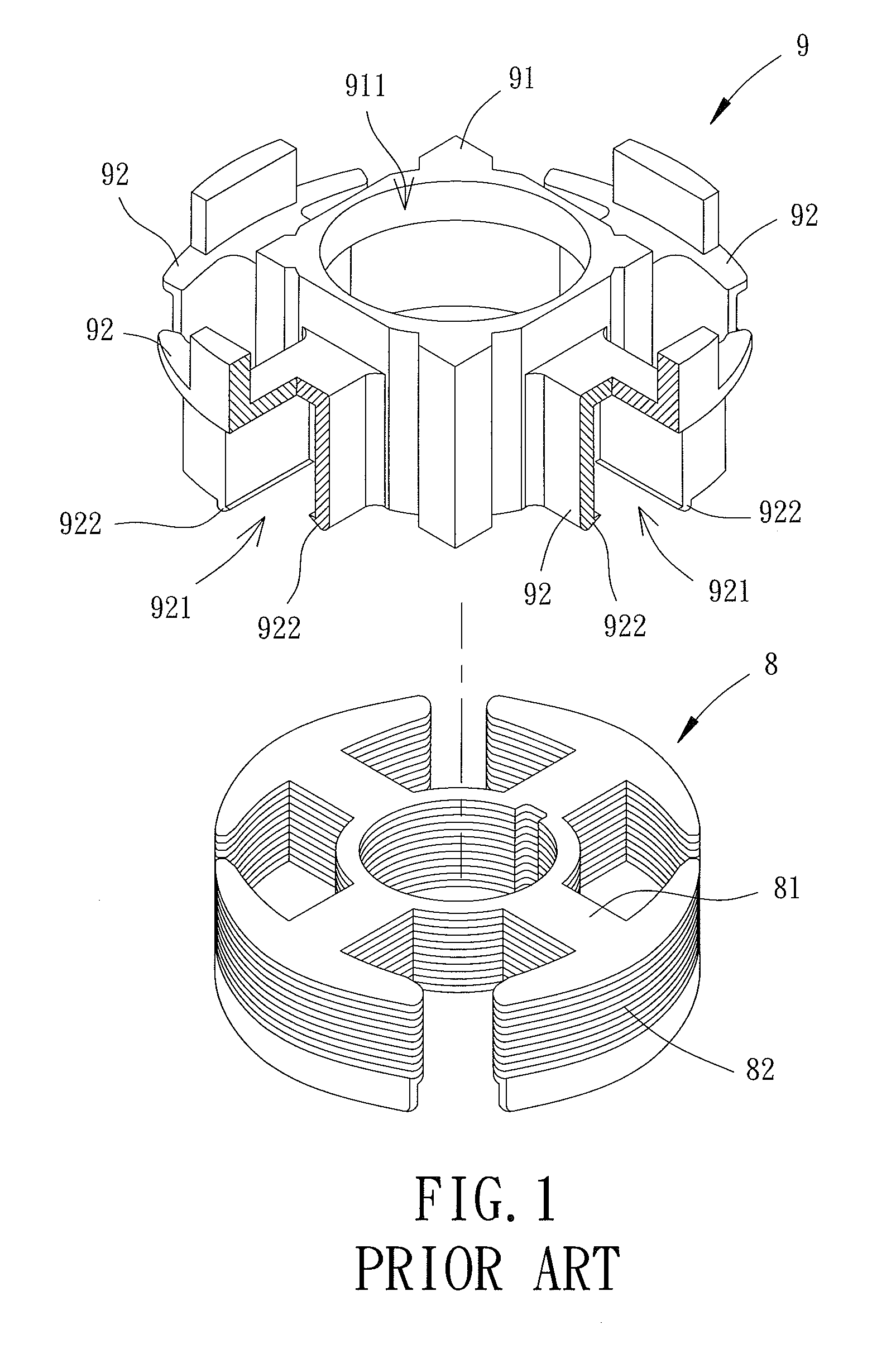
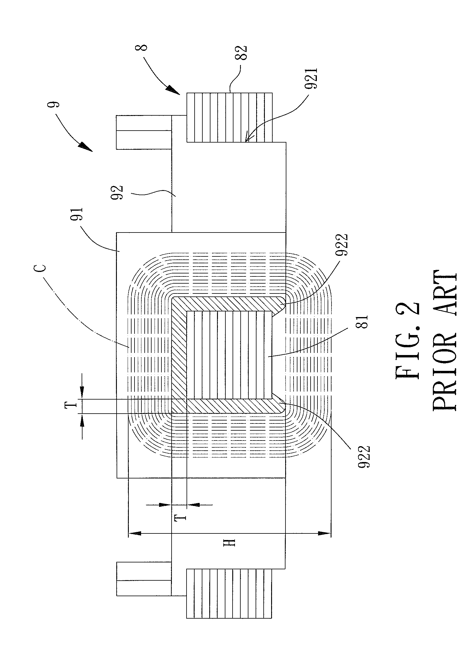
a stator and bobbin technology, applied in the direction of transformers/inductance coils/windings/connections, basic electric elements, electrical apparatus, etc., can solve the problems of reducing the structural strength of extension members and allowing extension members b>92/b> to be easily damaged
- Summary
- Abstract
- Description
- Claims
- Application Information
AI Technical Summary
Benefits of technology
Problems solved by technology
Method used
Image

Examples
first embodiment
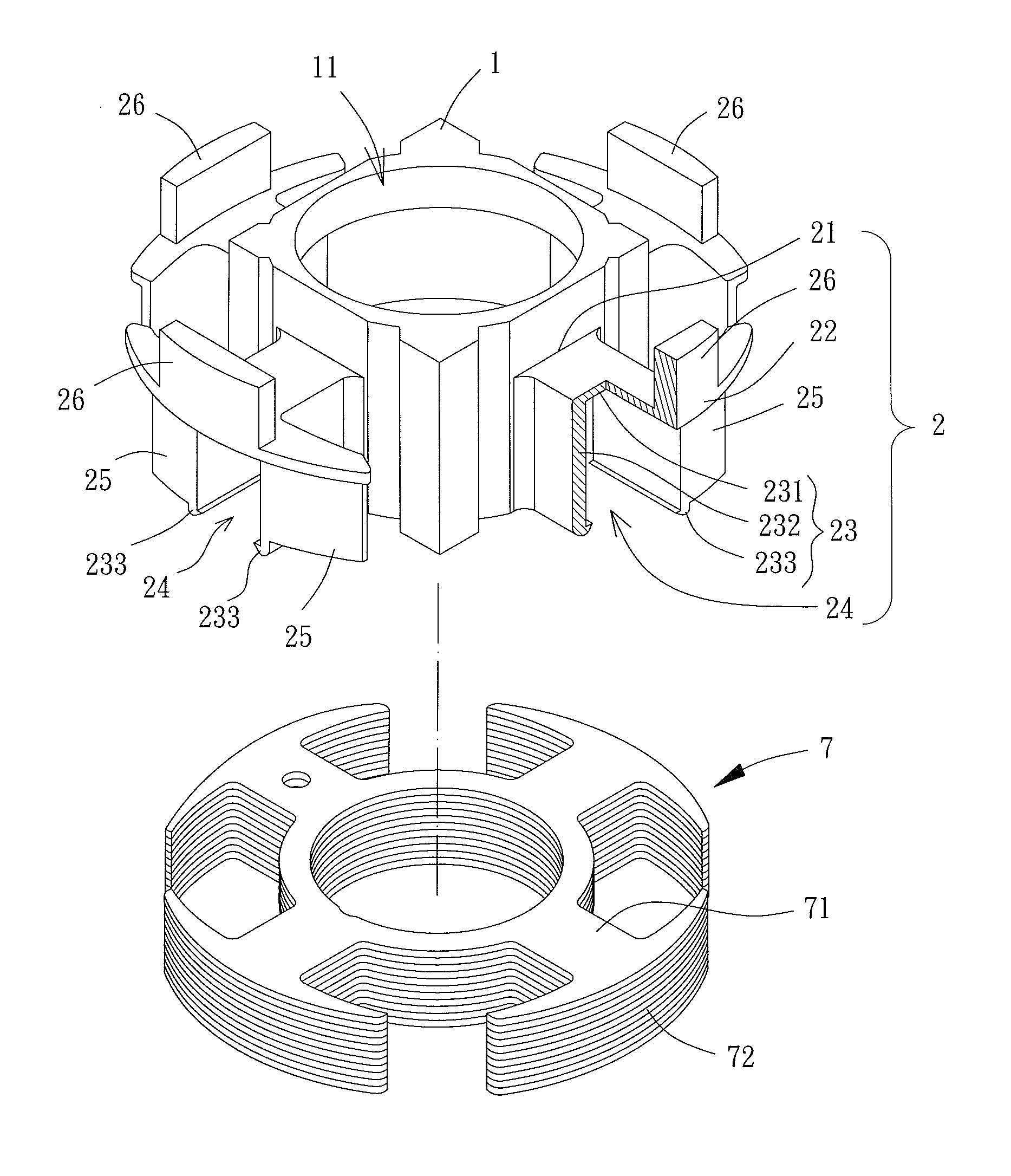
[0020]Referring to FIGS. 3 and 4, a single insulation bobbin of a stator of a motor is shown according to the invention. The insulation bobbin includes a body 1 and a plurality of extension members 2. The extension members 2, with equal distance, may be formed on an outer wall of the body 1 in an integral manner.
[0021]The body 1 is made of insulation material such as plastic. The body 1 has an assembly hole 11 extending in an axial direction so that the insulation bobbin may be fitted through the assembly hole 11 onto an outer circumferential wall of a bearing of the motor.
[0022]Each extension member 2 has a connection end 21, a free end 22, a wound portion 23, an accommodation room 24, two stop walls 25 and a standing wall 26. The connection end 21 and the free end 22 are respectively located on two ends of the extension member 2. The connection end 21 is connected to the body 1. The free end 22 has a wider width than the connection end 21 so that the extension member 2 resembles a...
second embodiment
[0027]In the second embodiment, the first body 1′ may be aligned and coupled with the second body 1″ to allow communication between the first assembly hole 11′ and the second assembly hole 11″. Based on this, the first and second insulation bobbins may be fitted onto a circumferential wall of a bearing of the motor through the first assembly hole 11′ and the second assembly hole 11″. In addition, the first extension members 2′ may be aligned and coupled with the second extension members 2″ to allow communication between the first accommodation room 24′ and the second accommodation room 24″, in which bottom faces of the two first stop walls 25′ abut against top faces of the two second stop walls 25″.
[0028]Particularly, referring to FIG. 6, taking the first wound portion 23′ and the second wound portion 23″ as an example, a thickness T3 of the first top plate 231′ may be smaller than a thickness T4 of the first side wall 232′, or a thickness T5 of the second top plate 231″ may be smal...
PUM
| Property | Measurement | Unit |
|---|---|---|
| thickness | aaaaa | aaaaa |
| distance | aaaaa | aaaaa |
| magnetic fields | aaaaa | aaaaa |
Abstract
Description
Claims
Application Information