Measurement apparatus and power cable accessory and system using the same and assembling method therefor

a technology of measuring apparatus and power cable, which is applied in the field of measuring variables, can solve the problems of reducing the rf (radio frequency) field generated by the antenna of the rfid tag in the space, failure of the power cable accessory on site, and increasing the temperature of the conductor of the power cable, so as to suppress the tendency for relative movement between the rfid tag and the electrical connector

Active Publication Date: 2019-10-17
ABB (SCHWEIZ) AG
View PDF0 Cites 2 Cited by
  • Summary
  • Abstract
  • Description
  • Claims
  • Application Information

AI Technical Summary

Benefits of technology

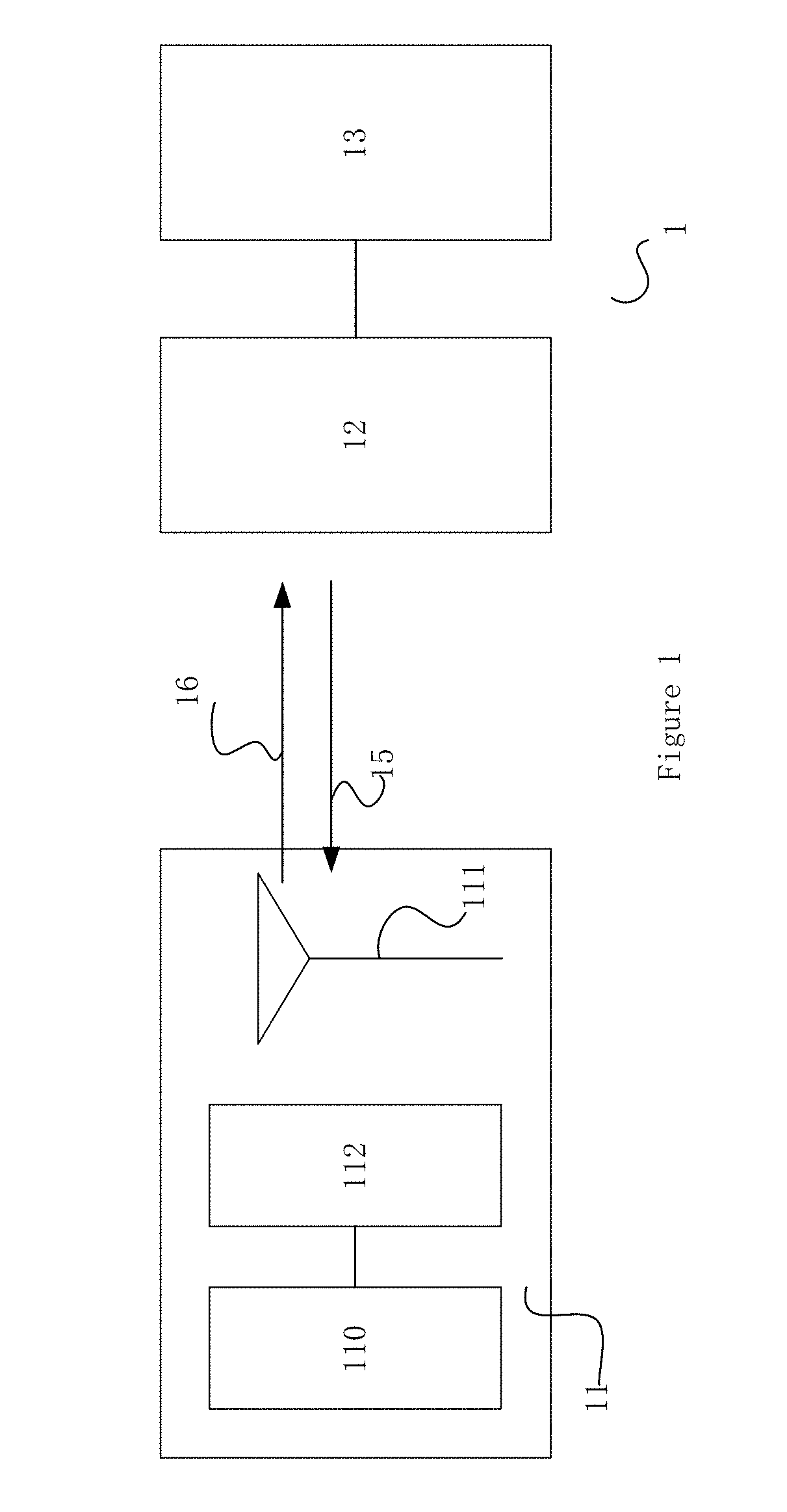
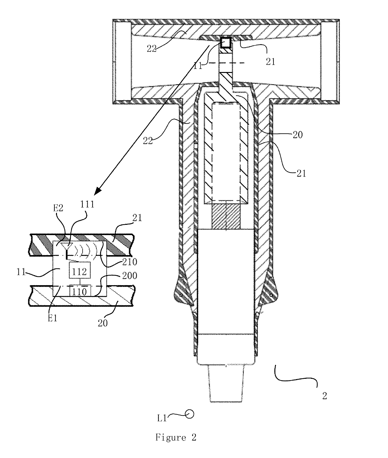
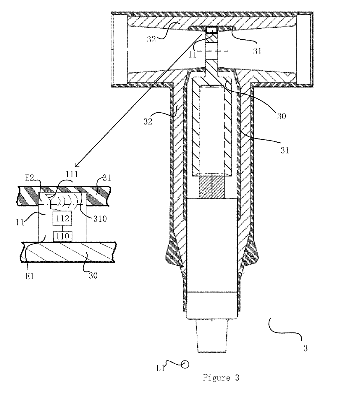
[0008]By having the antenna arranged outside of the electrical connecter, the reduction of RF field from the influence of the shielding from the electrical connecter may be ameliorated, and the coupling of RF signals between the RFID tag and an RFID reader becomes relatively strong. Due to the positioning of the antenna, the space in which the RF signals are blocked as a result of the RF shielding influence from the electrical connector decreases in the dimension. This allows larger room for positioning of the RFID reader with effective RF coupling with the RFID tag. The arrangement of placing the RFID reader in within the RF field becomes more flexible.
[0010]Preferably, a second end of the RFID tag is shaped to be fitted into a second groove of an assembly of a semi-conductive layer and an insulation layer of the power cable accessory; and the antenna of the RFID is arranged external to the semi-conductive layer. Because only a part of the RFID tag is held in the first groove leaving the other part sticking out of it, it is relatively easy for the RFID tag to reciprocate through the opening of the first groove By fitting the second end of the RFID tag into the second groove of the assembly of the semi-conductive layer and the insulation layer, both of the ends of the RFID tag are respectively secured to the electrical connecter and the semi-conductive layer, consequently the tendency for relative movement between the RFID tag and the electrical connector is suppressed.

Problems solved by technology

Some variable in relation to the power cable accessory may cause failure of the power cable accessory on site.
For example, the temperature of conductors of power cables may increase as currents carried by the power cables increase, and the conductor of the power cable accessory connecting the power cables normally will overheat in the first place and a fault may firstly happen at this weak point.
One possible disadvantage of the solution according to the patent is the reduction of the RF (radio frequency) field generated by the antenna of the RFID tag in the space due to electromagnetic shielding influence of the connector housing the antenna of the RFID tag.

Method used


Image

  • Measurement apparatus and power cable accessory and system using the same and assembling method therefor
  • Measurement apparatus and power cable accessory and system using the same and assembling method therefor
  • Measurement apparatus and power cable accessory and system using the same and assembling method therefor

Examples


Embodiment Construction

[0022]While the invention is susceptible to various modifications and alternative forms, specific embodiments thereof are shown by way of example in the drawings and will herein be described in detail. It should be understood, however, that the drawings and detailed description thereto are not intended to limit the invention to the particular form disclosed, but on the contrary, the intention is to cover all modifications, equivalents, and alternatives falling within the spirit and scope of the present invention as defined by the appended claims. Note, the headings are for organizational purposes only and are not meant to be used to limit or interpret the description or claims. Furthermore, note that the word “may” is used throughout this application in a permissive sense (i.e., having the potential to, being able to), not a mandatory sense (i.e., must).” The term “include”, and derivations thereof, mean “including, but not limited to”. The term “connected” means “directly or indire...


PUM

PropertyMeasurementUnit
semi-conductiveaaaaaaaaaa
thermal conductiveaaaaaaaaaa
poweraaaaaaaaaa

Abstract

An apparatus for measuring variable in relation to a power cable accessory, including: an RFID tag, including: a sensor configured to generate a signal indicative of the variable in its environment, an antenna, and an RFID IC electrically connected to the sensor and configured to process and modulate the signal generated by the sensor and transmit the modulated signal to an RFID reader via the antenna, wherein: the RFID tag is shaped to be fitted with the power cable accessory with its sensor in thermal contact with an electrical connector of the power cable accessory and with its antenna external to the electrical connector.

Description

TECHNICAL FIELD[0001]The invention relates to measuring variable in relation to a power cable accessory, and more particularly to measurement of the variable by use of RFID (radio-frequency identification) system in combination with a sensor.BACKGROUND ART[0002]In medium / high voltage power distribution systems, power cable accessories are used for connecting at least two medium-voltage / high-voltage conductors with one another. Power cable accessory is also referred as power cable joint, power cable connector, power cable termination, power cable head or insulating plug.[0003]Some variable in relation to the power cable accessory may cause failure of the power cable accessory on site. For example, the temperature of conductors of power cables may increase as currents carried by the power cables increase, and the conductor of the power cable accessory connecting the power cables normally will overheat in the first place and a fault may firstly happen at this weak point. Thus, measurin...

Claims


Application Information

Patent Timeline
Patent Type & Authority Applications(United States)
IPC IPC(8): G01K1/02G06K7/10G06K19/07
CPCG01K1/024G06K19/0717G06K7/10366G06K19/0723G01R31/66
Inventor ZHANG, YIBOCHEN, JIANSHENGHE, JIANQIAO, BOLI, CHUN
Owner ABB (SCHWEIZ) AG
Why Eureka
Try Eureka