Electrical power terminal fastened to a wire connection member

a technology of electrical power terminals and connection members, which is applied in the direction of coupling contact members, riveted connections, coupling device connections, etc., can solve the problems of increasing the power supply necessary for such electrically driven vehicles or hybrid vehicles, increasing not only the cost but also the associated problems, and reducing the diameter of the terminal element. , the effect of saving a significant spa

Inactive Publication Date: 2015-02-03
APTIV TECH LTD
View PDF12 Cites 3 Cited by
  • Summary
  • Abstract
  • Description
  • Claims
  • Application Information

AI Technical Summary

Benefits of technology

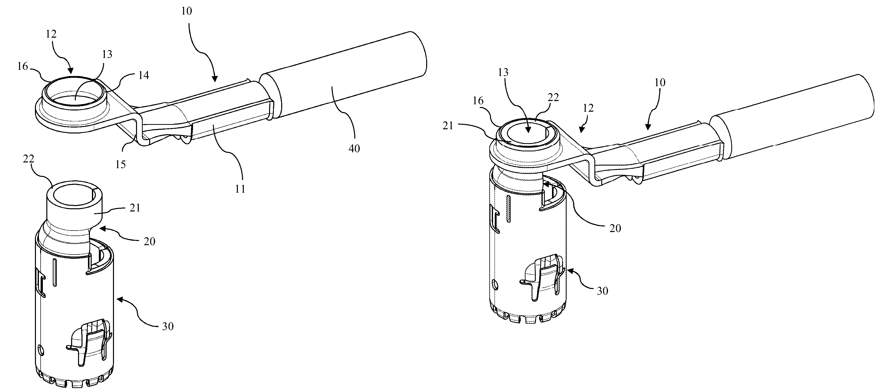
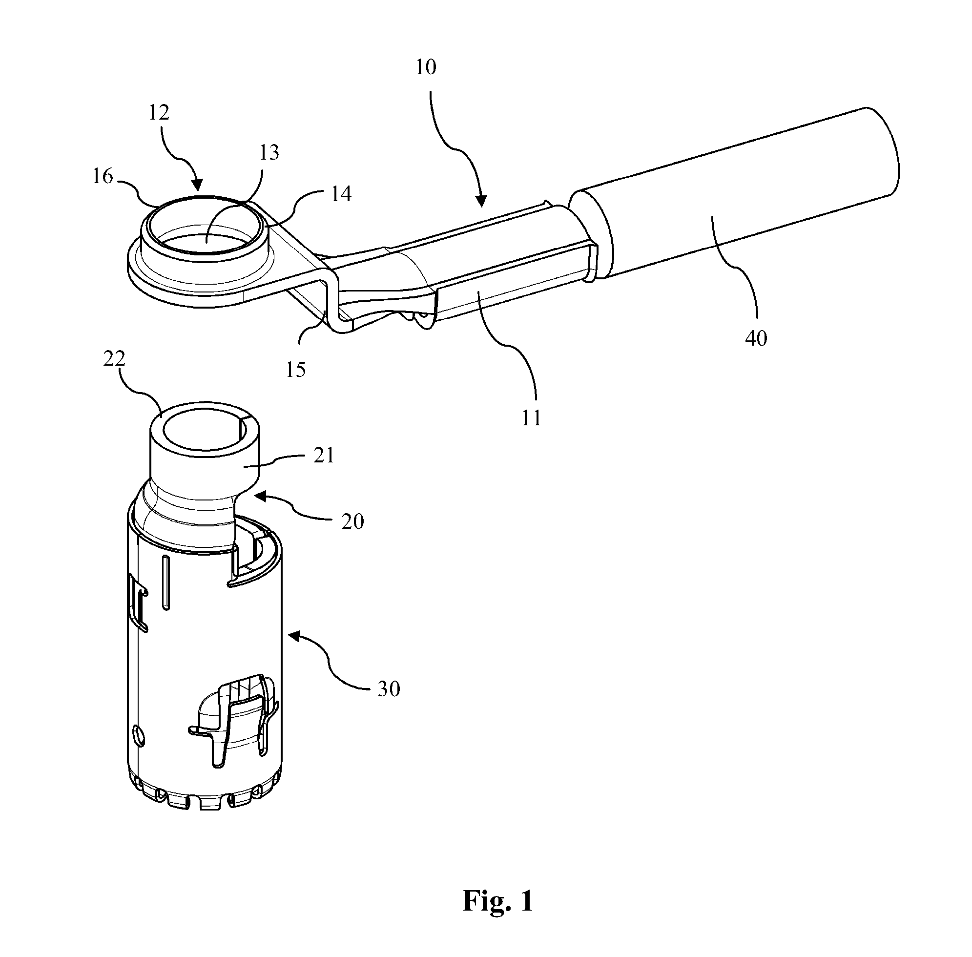
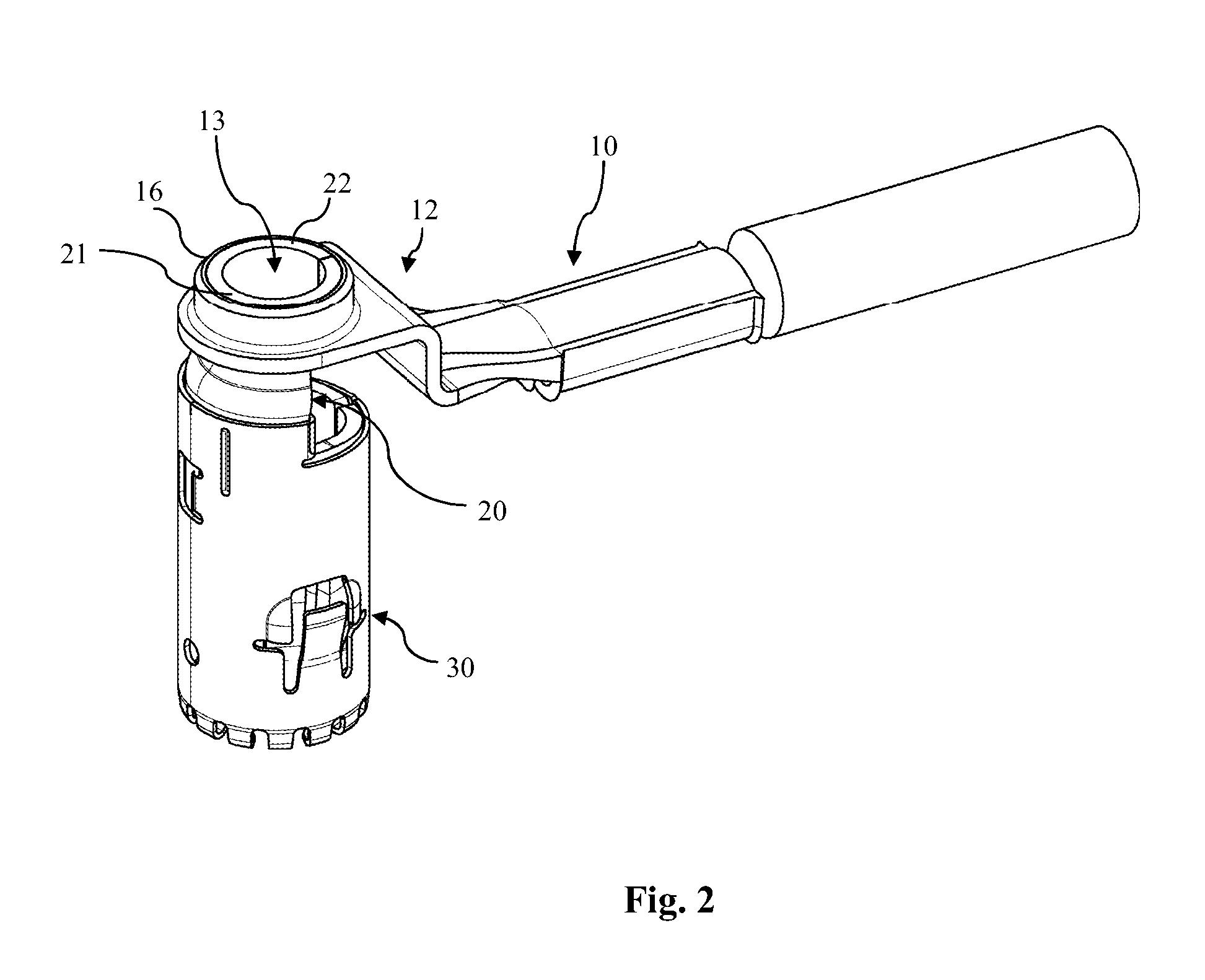
[0005]According to the invention, an electrical power terminal is provided comprising at least two parts preferably adapted to be assembled with each other: an elongated wire connection member and a corresponding terminal element. Thus, the power terminal is made from two distinct parts and has a modular design, such that for example the same wire connection member may be used with different terminal elements, so that the terminal element may be exchanged for different applications in for example different vehicles but the wire connection member is standardized and thus usable in any kind of situation. The wire connection member is for example made from a piece of stamped sheet metal. It has in any case a wire fastening portion for the attachment of a wire or cable and a terminal fastening portion, preferably at the opposite end of the connection member in relation to the wire fastening portion, which comprises a round opening for the reception of a part of the terminal element. The terminal element of the present invention has essentially cylindrical shape and comprises a terminal end and a connecting end, whereby the connecting end is adapted to be received in the round, in particular circular opening of the fastening portion for the terminal element. Thereby, upon connecting, the terminal element and the elongated wire connection member are arranged essentially perpendicular to each other so that the necessity to bend e.g. an electrical power cable is eliminated. The diameter of the terminal element is reduced at the connecting end thereof compared to the main body of the essentially cylindrical terminal element. Then this external dimension of the terminal fastening portion can be reduced to as to not extend laterally (except in the portion linked to the wire fastening portion) more than the external diameter of the terminal element, though it remains material for a robust connection of the terminal element with the wire connection member. Such a feature allows in particular saving a significant room when several connectors according to the invention are placed side by side. Thereby, a particular compact design is realized, which is nevertheless stable and strong enough to fulfill all the necessary mechanical requirements in particular in automotive applications.
[0007]In a further preferred embodiment, the terminal element is formed from a piece of rolled sheet metal. In this way, the cylindrical shape of the terminal element can be provided in a very economic manner. Preferably, the outer diameter of the connecting end of the terminal element is slightly larger than the inner diameter of the round, in particular circular opening, whereby the respective diameters are chosen that it is still possible to insert the connecting end into the opening when sufficient force is applied. If the terminal element is formed from a rolled piece of sheet metal it is preferred that a gap remains at the joint of the two adjacent edges of the piece of sheet metal, at least at the connecting end of the terminal element. Due to the gap it is possible to elastically press the connecting end upon insertion into the round in particular circular opening of the elongated wire connection member, thereby facilitating the assembly process.
[0008]To improve the mechanical connection between the wire connection member and the terminal element it is preferred that the round, in particular circular opening is surrounded by a cylindrical collar projecting perpendicular from the plane defined by the round opening. In this way the terminal surface between wire connection member and terminal element is increased, which leads in particular in the case of a press fitting engagement to increased holding forces between terminal element and wire connection member.
[0009]Preferably, the wire connection member is provided with a step between the wire fastening portion and the fastening portion for the terminal element. This step allows a particular compact design of the inventive power terminal, in particular if an additional sealing member is provided around the wire connection member. Then the total height of the terminal does not exceed the height of the terminal element. However, is that the step offers the possibility for an additional locking feature and / or an additional Terminal Position Assurance (TPA) member. By introducing a locking element as e.g. a locking slider or bar into the edge formed by the step after mounting of the terminal inside of a connector housing, it can be prevented that the terminal is unintentionally removed again from its correct position in the housing. Likewise, if constructed accordingly, one can make sure that the locking element can only be introduced into the edge formed by the step if the terminal is correctly positioned in its respective housing (TPA functionality).
[0011]The inventive design of the electrical power terminal allows a flexible application of the power terminal due to its modular design and the simple mounting process. Since the connecting end of the terminal element is preferably held in the round opening of the terminal fastening portion by a press fitting engagement it is possible to dismount the terminal element from the wire connection member, for example for service purposes. Still further, due to the two distinct parts forming the inventive power terminal it is possible to choose different materials for the two members, each being optimized for its respective purpose.

Problems solved by technology

The electrical power supply necessary for such electrically driven vehicles or hybrid vehicles is considerably larger than with ordinary fuel driven vehicles, which only need electrical power for example for certain comfort or safety features, but not for the propulsion of the vehicle itself.
Thus, the commonly used electrical power terminals of ordinary fuel driven vehicles are not usable in connection with the high current or voltage necessary for electrical or hybrid vehicles.
The electrical terminals as well as the wiring in electrical or hybrid cars have to be dimensioned more massively, which increases not only the costs but also the problems associated with the larger space requirements of such terminals and the corresponding wiring.
For example, due to the larger diameter of the power supply lines, which is in the range of several mm, as for example 10 mm, the bending radius of such a cable is necessarily comparably large, which is highly problematic in the cramped engine compartments of modern passenger vehicles.
This is even more true for electrical or hybrid systems in which space is a particular problem due to the large size of the required batteries and / or due to the fact that two drive units have to be arranged somewhere in the vehicle.

Method used


Image

  • Electrical power terminal fastened to a wire connection member
  • Electrical power terminal fastened to a wire connection member
  • Electrical power terminal fastened to a wire connection member

Examples


Embodiment Construction

[0020]FIG. 1 is a schematic illustration of an exemplary electrical 90° (orthogonal) power terminal in accordance with the invention. The power terminal comprises an elongated wire connection member 10 as well as a terminal element 20. The wire connection member 10 is made from a stamped and bent piece of sheet metal (copper, aluminum, metal alloy, etc.) and is provided with a wire fastening portion 11 on one end and a terminal fastening portion 12 onto the terminal element 20, on the opposite end thereof. In the figures, a power line cable 40 is schematically shown, which is attached to the wire fastening portion 11 by means of a crimping or welding operation. The terminal fastening portion 12 comprises a circular opening 13 which is adapted to receive a connecting end 21 of the terminal element 20. The circular opening 13 is surrounded by a collar 14 which is of essentially cylindrical shape and projects upwardly from the plane of the circular opening 13 as one can see from FIG. 1...


PUM


Abstract

The present invention relates to an electrical 90° power terminal, comprising an elongated wire connection member, and a terminal element. The wire connection member is provided with a wire fastening portion and a fastening portion for the terminal element comprising a circular opening, and the terminal element has an essentially cylindrical shape and comprises a terminal end and a connecting end adapted to be received in the circular opening of the fastening portion. When connected with each other, the terminal element and the elongated wire connection member are arranged essentially perpendicular to each other.

Description

CROSS-REFERENCE TO RELATED APPLICATIONS[0001]This application is a national stage application under 35 U.S.C. §371 of PCT Application No. PCT / IB2011 / 002084 having an international filing date of Aug. 10, 2011, which designated the United States, which PCT application claimed the benefit of PCT Application No. PCT / IB2010 / 002446, filed Aug. 19, 2010, the entire disclosure of each of which are hereby incorporated herein by reference.FIELD OF THE INVENTION[0002]The invention relates to electrical power terminals, in particular for the application in electrical or hybrid passenger vehicles.BACKGROUND OF THE INVENTION[0003]Electrical power terminals or connectors are used to connect electrical appliances with each other and in particular to transmit the necessary electrical power between a power source, as for example a battery or generator, and an electric device as for example an electric motor. In particular when used in connection with passenger vehicles, such electrical power connect...

Claims


Application Information

Patent Timeline
Patent Type & Authority Patents(United States)
IPC IPC(8): H01R4/28H01R4/06H01R11/12H01R13/05H01R13/15
CPCH01R13/15H01R4/06H01R11/12H01R13/052H01R2201/26H01R13/111
Inventor SCHMIDT, RAINERPABST, THOMAS BERNHARD
Owner APTIV TECH LTD
Why Eureka
Try Eureka