Receivers for television signals

a television signal and receiver technology, applied in the field of television signal receivers, can solve the problems of increasing the amount of time that can be recorded in cyclic files, complex, and difficult to compress without introducing unwanted artefacts, and achieve the effect of converting the file from a buffer

Inactive Publication Date: 2012-03-29
SKY CP LTD
View PDF6 Cites 3 Cited by
  • Summary
  • Abstract
  • Description
  • Claims
  • Application Information

AI Technical Summary

Benefits of technology

[0014]Thus, the amount of stored data is determined by the duration of the information the data represents, e.g. by the length of stored video or stored television signals when viewed as normal. This has the advantage of being able to provide a buffer, e.g. for a television signal, that has a maximum capacity defined by the duration of the information it is intended to contain, e.g. a television programme of say 30 minutes, rather than the amount of data that can be stored in the buffer, e.g. 2 gigabytes. This is far more predictable for a user as the user can be more certain of the length of the stored information stream. Provided enough data has been received and stored to reach the given period, the storage device, memory or buffer will always store data representing substantially the given period of the information stream.
[0020]As it was always necessary for the cyclic files of the prior art to be large enough to cover the worst case, i.e. to store (say) 30 minutes of data received at the maximum data rate, these cyclic files took up a large amount of memory space. However, memory space can be allocated to the stored data of the invention dynamically, as the amount of stored data is monitored according to the duration of the information it represents. Thus, during periods of low received data rate, the file in which the data is stored can be smaller than during periods of high received data rate. Memory space can therefore be allocated to the file and to other applications or other stored data more efficiently. In other words, the need in the prior art to reserve memory space which is surplus to requirements during periods of low received data rate is obviated by the invention.
[0027]Unlike the prior art, the oldest data is not simply overwritten. Rather new data is added to the end of the data file as if it were a linear file. The start of the data file is redefined to maintain the size of the file and as the start of the file is moved, the memory used by the oldest data is returned to the memory for general use. Thus, at any particular time, the data file actually resembles a linear file, and can therefore be converted to such simply by stopping the deletion process. Thus, conversion of the file from a “buffer” to a linear file is straightforward.

Problems solved by technology

As memory costs have fallen and sizes of, for example, hard disk memories have increased, the amount of time that can be recorded in cyclic files has increased.
A frame of video showing, say, a crowd scene is generally much more complex than a frame of video showing, say, a commentator in front of a plain background and thus will be more difficult to compress without introducing unwanted artefacts.
Similarly, video including significant changes between frames, such as video of fast moving scenes, is generally more complex than slower changing video.
It is therefore not possible to know in advance how much disk space will be required to store data for 30 minutes (say) of a programme when VBR encoding is used.
Again, it is therefore very difficult to determine, in advance, the size of a cyclic file that will be required to store 30 minutes (say) of a given programme.
This is wasteful of disk space.
Having to dedicate memory for the greatest possible memory requirement for the cyclic file also limits the user's choice.
It may also be unpredictable for a user, as the user is not certain whether the cyclic file contains 30 minutes (say) of a programme, more or less.

Method used


Image

  • Receivers for television signals
  • Receivers for television signals
  • Receivers for television signals

Examples


Embodiment Construction

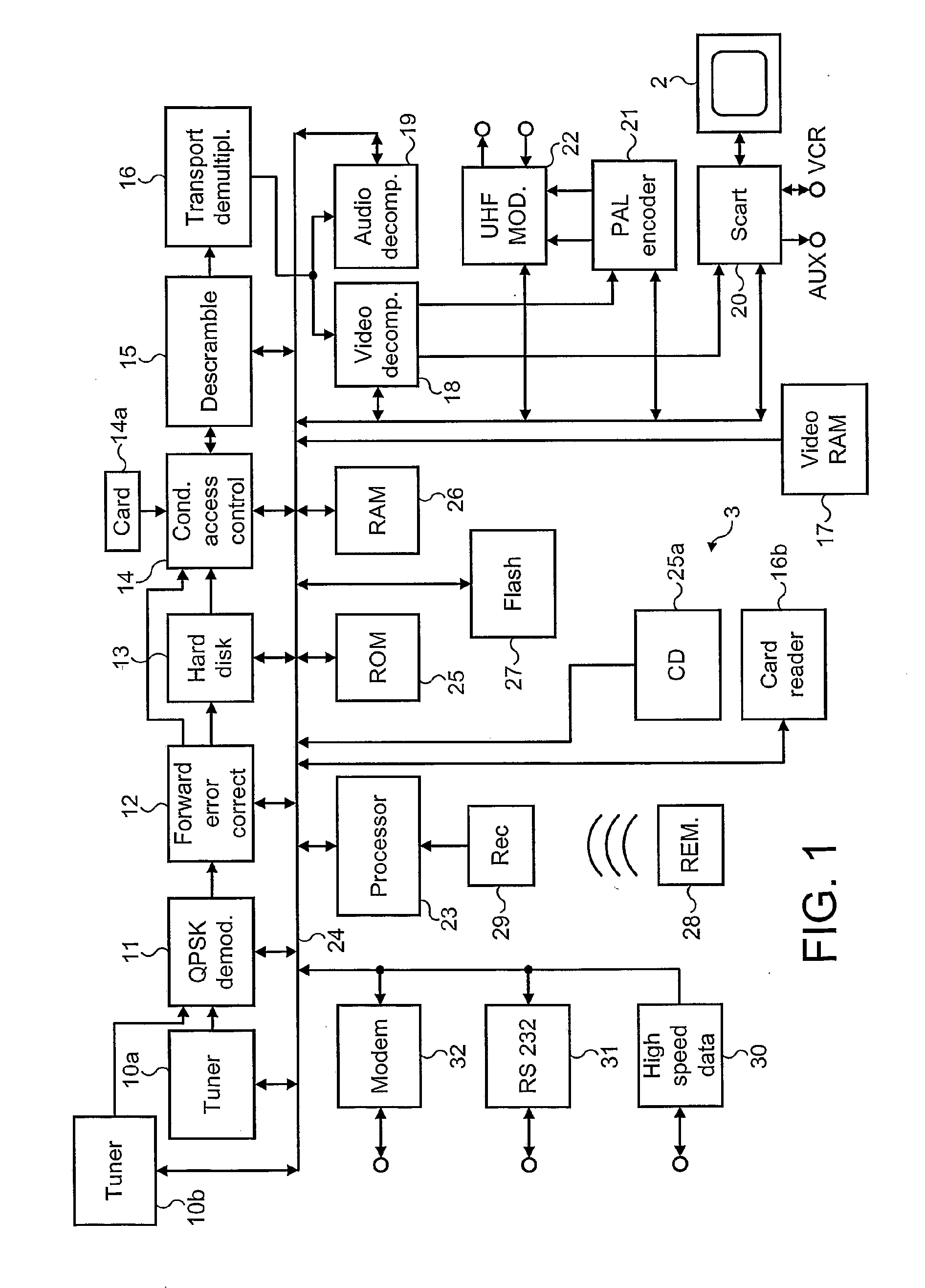
[0051]FIG. 1 of the accompanying drawings shows a “set top box” or receiver 3 for receiving television signals from a satellite television broadcast network. In this example, received signals are input to first and second tuners 10a and 10b but any plural number of tuners may be used in the receiver 3. The tuners 10a and 10b are tuneable into the same or different channels of the satellite television broadcast network for simultaneous reception of the same or different television programmes. Signals from the first and second tuners 10a and 10b are passed to a Quadrature Phase Shift Key (QPSK) demodulator 11. Demodulated signals are error-corrected by way of a forward error corrector circuit 12. The receiver 3 has a hard disk 13 which receives from the forward error corrector circuit 12 compressed video and audio data representing received television programmes for recording and subsequent playback, as described in greater detail below.

[0052]The received signals comprise digitally en...


PUM


Abstract

A television signals receiver for receives and stores television signals encoded at a variable data rate. Time information is generated based on the time of receipt of the signals that defines the duration of the television signals when output in decompressed form at a substantially constant data rate. The received signals are then written to a file on a hard disk 13 in received order together with the time information. The time information of signals stored in the file is monitored and old signals are deleted from the file such that the file stores signals corresponding to a predetermined period of time.

Description

CROSS-REFERENCE TO RELATED APPLICATIONS[0001]The present application is a divisional application under 35 USC §121 which claims priority under 35 USC §120 to U.S. application Ser. No. 10 / 495,546, filed on 7 Dec. 2004, which is a national stage filing under 35 USC §371 of International Application Serial No. PCT / GB02 / 05109, filed on 13 Nov. 2002. The present application is also related to and claims priority under 35 USC §119(e) to Great Britain patent application Serial No. 0127234.3 filed on 13 Nov. 2001. Each application is incorporated herein by reference.FIELD OF THE INVENTION[0002]This invention relates to methods and apparatus for recording television signals for subsequent playback and, more specifically, to improvements in the storage of data representing television signals and such like and improvements in the control of recording and playback.BACKGROUND OF THE INVENTION[0003]In recent years there has been a move towards broadcasting television signals in digital form. Suit...

Claims


Application Information

Patent Timeline
Patent Type & Authority Applications(United States)
IPC IPC(8): H04N5/76H04N5/91H04N1/00H04N5/765H04N5/775H04N5/781H04N5/782H04N5/92H04N9/804H04N21/433H04N21/458H04N21/472H04N21/488
CPCH04N5/76H04N5/765H04N5/775H04N5/781H04N5/782H04N21/433H04N21/4334H04N21/4583H04N21/47214H04N21/4882H04N9/8042
Inventor WILLAME, XAVIERBODKIN, NIGELJAMES, NICHOLASCOLLINS, ELLEN FIONAFREEMAN, BENJAMIN JOHNATHANSULLIVAN, BRIAN FRANCIS
Owner SKY CP LTD
Why Eureka
Try Eureka