Fluid-working machine and method of operating a fluid-working machine

a technology of fluid-working machines and working machines, which is applied in the direction of positive displacement liquid engines, piston pumps, instruments, etc., can solve the problems of excessive flow and pressure overshoot, dramatic impairment of the function of the fluid-working machine, and failure to function adequately

Active Publication Date: 2012-03-29
ARTEMIS INTELLIGENT POWER
View PDF8 Cites 18 Cited by
  • Summary
  • Abstract
  • Description
  • Claims
  • Application Information

AI Technical Summary

Benefits of technology

[0014]The taking into account of the availability of other working chambers when selecting the volume of working fluid to be displaced by a working chamber enables the fluid-working machine to displace an appropriate amount of fluid to meet a working function, responsive to a received demand signal, despite changes in the availability of working chambers. The displacement of working fluid to carry out the working function can be smoother and more closely follow the displacement indicated by the demand signal than would otherwise be the case if the availability of other working chambers was not taken into account.
[0036]Thus, the fault confirmation procedure may be implemented so as to identify a fault or faults in one or more working chambers without causing a substantial change in the output of the fluid working machine, except briefly in the event that a fault is identified. For example, the controller may detect that the fluid pressure or flow output is oscillating, in the manner shown in FIG. 1, and cause the fault confirmation procedure to be executed. Changing the volume of fluid to be displaced by one or more of the working chambers without changing the expected output of the fluid-working machine (such as by substituting one or more active cycles of a working chamber for one or more active cycles of another working chamber) enables the fluid-working machine to continue to meet a working function and respond to a demand signal whilst the fault confirmation procedure is carried out.
[0093]The fault detection module may determine whether the measured output parameter fulfils at least one acceptable function criterion a period of time after a selection of a net displacement of working fluid by a working chamber during a specific cycle of working chamber volume. It may not be necessary to consider whether the measured output parameter fulfils at least one acceptable function criterion following the selection of an idle cycle in which there is no net fluid displacement. Thus, the controller may be operable to intersperse idle cycles in which no net displacement of working fluid by a working chamber is selected and active cycles in which a net displacement of working fluid by the same working chamber is selected (that is to say, selection of an active cycle), and inhibit or prevent the fault detection module determining whether the measured output parameter fulfils the at least one acceptable function criterion responsive to selection of no net displacement of working fluid by a working chamber (that is to say, selection of an idle cycle).

Problems solved by technology

In the event that one or more working chambers of a fluid-working machine comprising a plurality of working chambers become unavailable, for example if a fault occurs in one or more working chambers or in the control of one or more working chambers, the function of the fluid-working machine is dramatically impaired.
In response, the vehicle slows down, so when the controller returns to that part of the repeating pattern that does not use the deactivated working chamber, there is an excess of flow and a pressure overshoot.
Thus, known fluid-working machines, which, in the event of the unavailability of one or more working chambers, issue output signals to meet a demand signal as though all of the working chambers were available, fail to function adequately when a working chamber is unavailable.

Method used


Image

  • Fluid-working machine and method of operating a fluid-working machine
  • Fluid-working machine and method of operating a fluid-working machine
  • Fluid-working machine and method of operating a fluid-working machine

Examples


Embodiment Construction

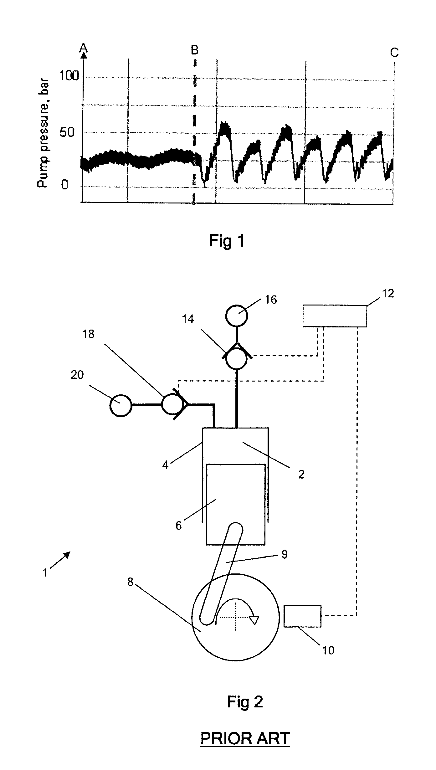
[0132]FIG. 2 is a schematic diagram of a known fluid-working machine 1. The net throughput of fluid is determined by the active control of electronically controllable valves, in phased relationship to cycles of working chamber volume, to regulate fluid communication between individual working chambers of the machine and fluid manifolds. Individual chambers are selectable by a controller, on a cycle by cycle basis, to either displace a predetermined fixed volume of fluid or to undergo an idle cycle with no net displacement of fluid, thereby enabling the net throughput of the pump to be matched dynamically to demand.

[0133]With reference to FIG. 2, an individual working chamber 2 has a volume defined by the interior surface of a cylinder 4 and a piston 6, which is driven from a crankshaft 8 by a crank mechanism 9 and which reciprocates within the cylinder to cyclically vary the volume of the working chamber. A shaft position and speed sensor 10 determines the instantaneous angular posi...


PUM


Abstract

In a method of operating a fluid-working machine, the volume of working fluid displaced during each cycle of working chamber volume is selected taking into account the availability of other working chambers. The status of each working chamber is monitored and a working chamber treated as unavailable if it is found to be malfunctioning. A working chamber may be treated as unavailable if it is allocated to an alternative working function. A fault may be detected in a working chamber by determining whether a measured output parameter of the fluid working machine fulfils at least one acceptable function criterion taking into account the previously selected net displacement of working fluid by a working chamber during a cycle of working chamber volume to carry out the working function.

Description

FIELD OF THE INVENTION[0001]The invention relates to fluid-working machines comprising a plurality of working chambers of cyclically varying volume, each said working chamber operable to displace a volume of working fluid which is selectable for each cycle of working chamber volume, and to methods of operating such fluid-working machines.BACKGROUND TO THE INVENTION[0002]It is known to provide fluid-working machines, such as pumps, motors and machines which operate as either a pump or a motor, which include a plurality of working chambers of cyclically varying volume, in which the flow of fluid between the working chambers and one or more manifolds is regulated by electronically controlled valves. Although the invention will be illustrated with reference to applications in which the fluid is a liquid, such as a generally incompressible hydraulic liquid, the fluid could alternatively be a gas.[0003]For example, fluid-working machines are known which comprise a plurality of working cha...

Claims


Application Information

Patent Timeline
Patent Type & Authority Applications(United States)
IPC IPC(8): F04B49/06G16Z99/00
CPCF04B7/0076F04B53/1082F04B51/00G16Z99/00F04B7/00F04B49/06F04B53/10F04B1/06F04B49/24
Inventor RAMPEN, WILLIAM HUGH SALVINCALDWELL, NIALL JAMESLAIRD, STEPHEN MICHAEL
Owner ARTEMIS INTELLIGENT POWER
Why Eureka
Try Eureka