Drive System For A Mobile Sprayer And/Or For A Mobile Blower

a technology of drive system and sprayer, which is applied in the field of drive system for mobile sprayer and/or for mobile blower, can solve the problems of damage to crops, leakage of hydraulic drive system, and high cost of hydraulic hosing and hydraulic fluid to directly power the motor provided for each fan, so as to reduce the maintenance level and reduce the weight of the system

a technology of drive system and sprayer, which is applied in the field of drive system for mobile sprayer and/or for mobile blower, can solve the problems of damage to crops, leakage of hydraulic drive system, and high cost of hydraulic hosing and hydraulic fluid to directly power the motor provided for each fan, so as to reduce the maintenance level and reduce the weight of the system

US20120085836A1Inactive Publication Date: 2012-04-12CROPLANDS EQUIP

Image

  • Drive System For A Mobile Sprayer And/Or For A Mobile Blower
  • Drive System For A Mobile Sprayer And/Or For A Mobile Blower
  • Drive System For A Mobile Sprayer And/Or For A Mobile Blower

Examples


Embodiment Construction

[0075]Reference will now be made to illustrations of drive systems and mobile sprayers that embody the above general principles of the present invention. However, it is to be understood that the following description is not to limit the generality of the above description.

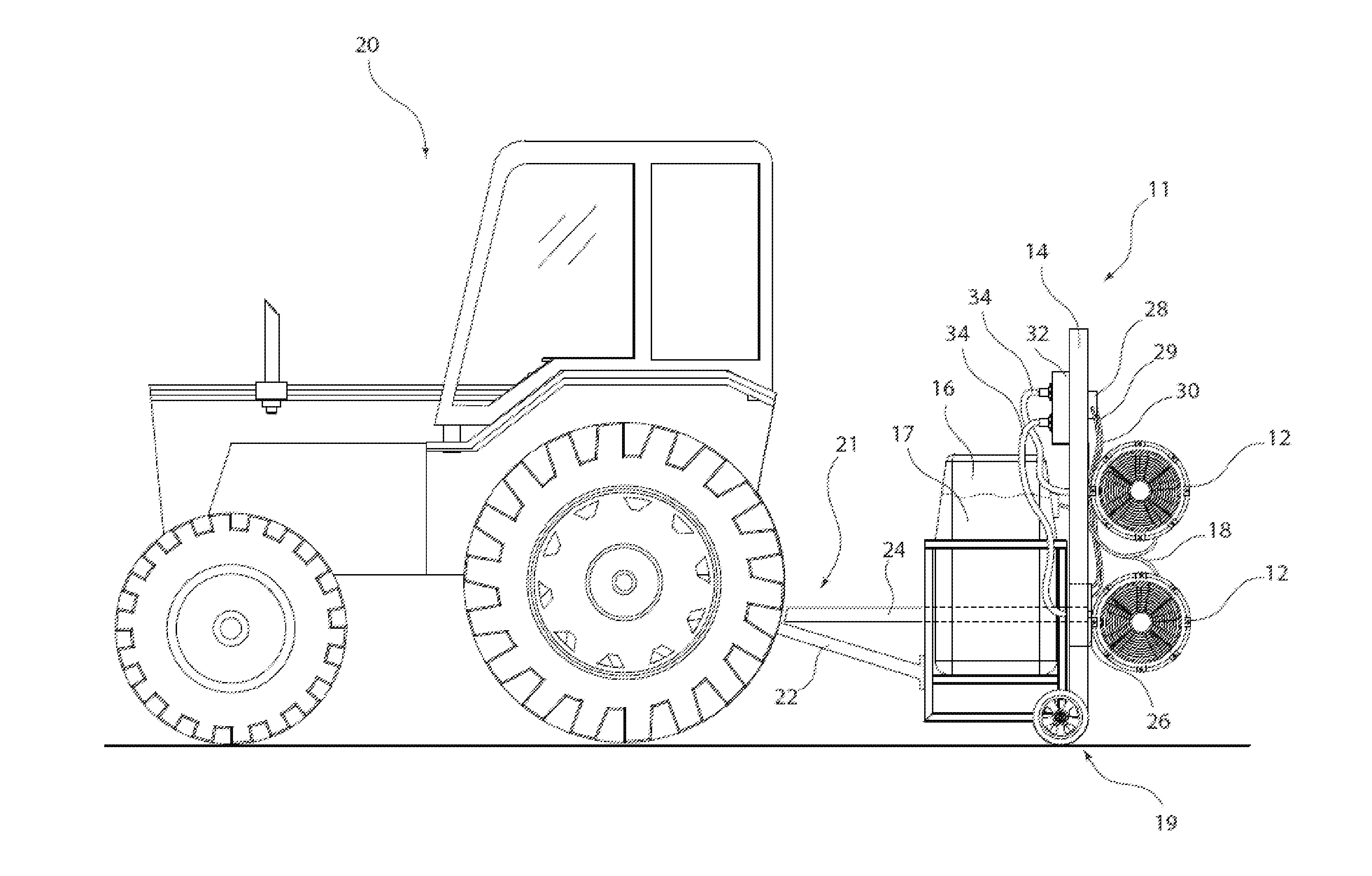
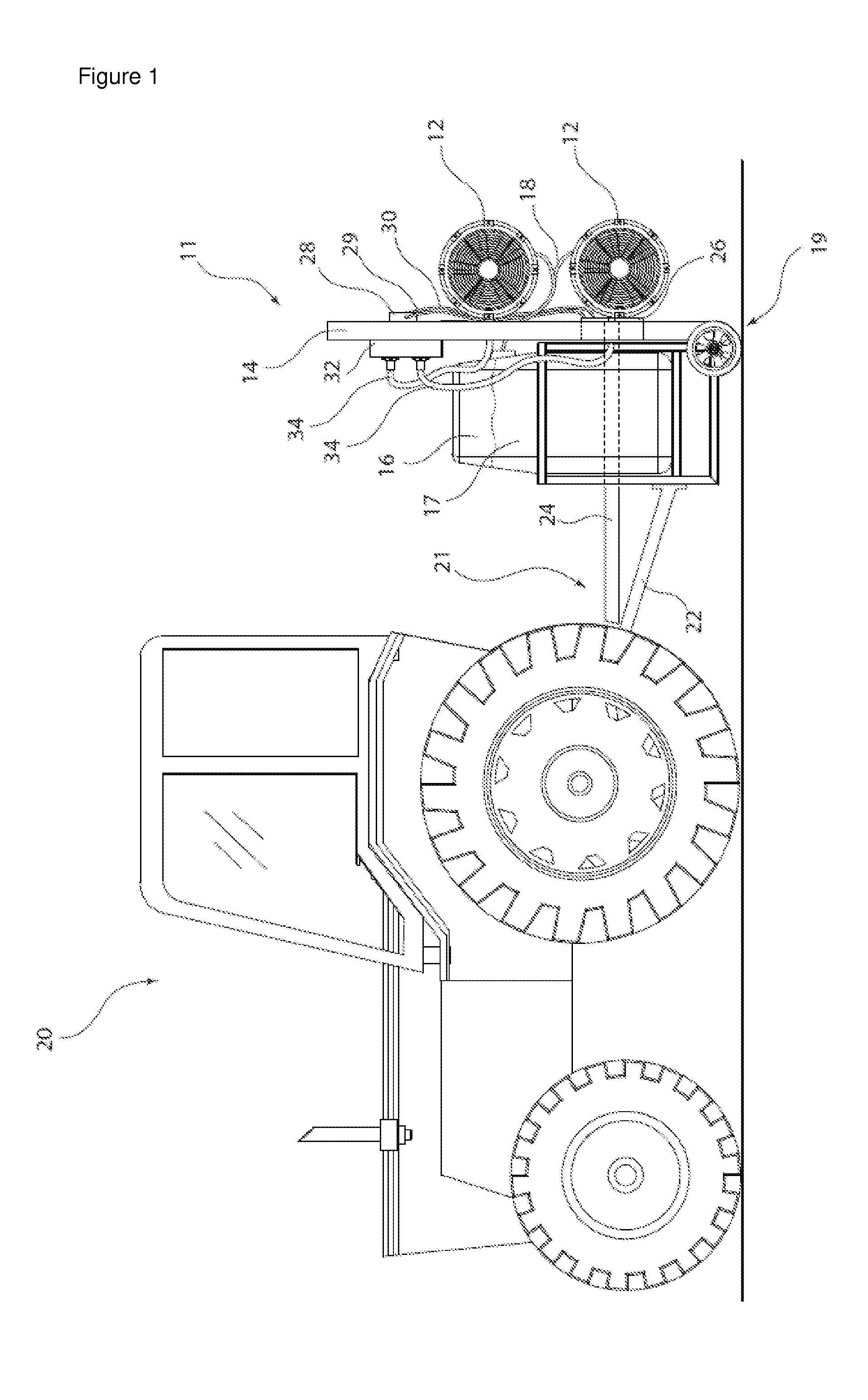
[0076]A mobile sprayer 11, which includes the drive system of the invention and is illustrated in the drawings, will be described in relation to the application of a liquid 17 to plants 10. The mobile sprayer 11 is towed by a tractor 20 between rows of plants 10. In addition to driving the tractor 20, the power from the tractor 20 is used to operate fan units 12 of the mobile sprayer 11, as will be described in detail below.

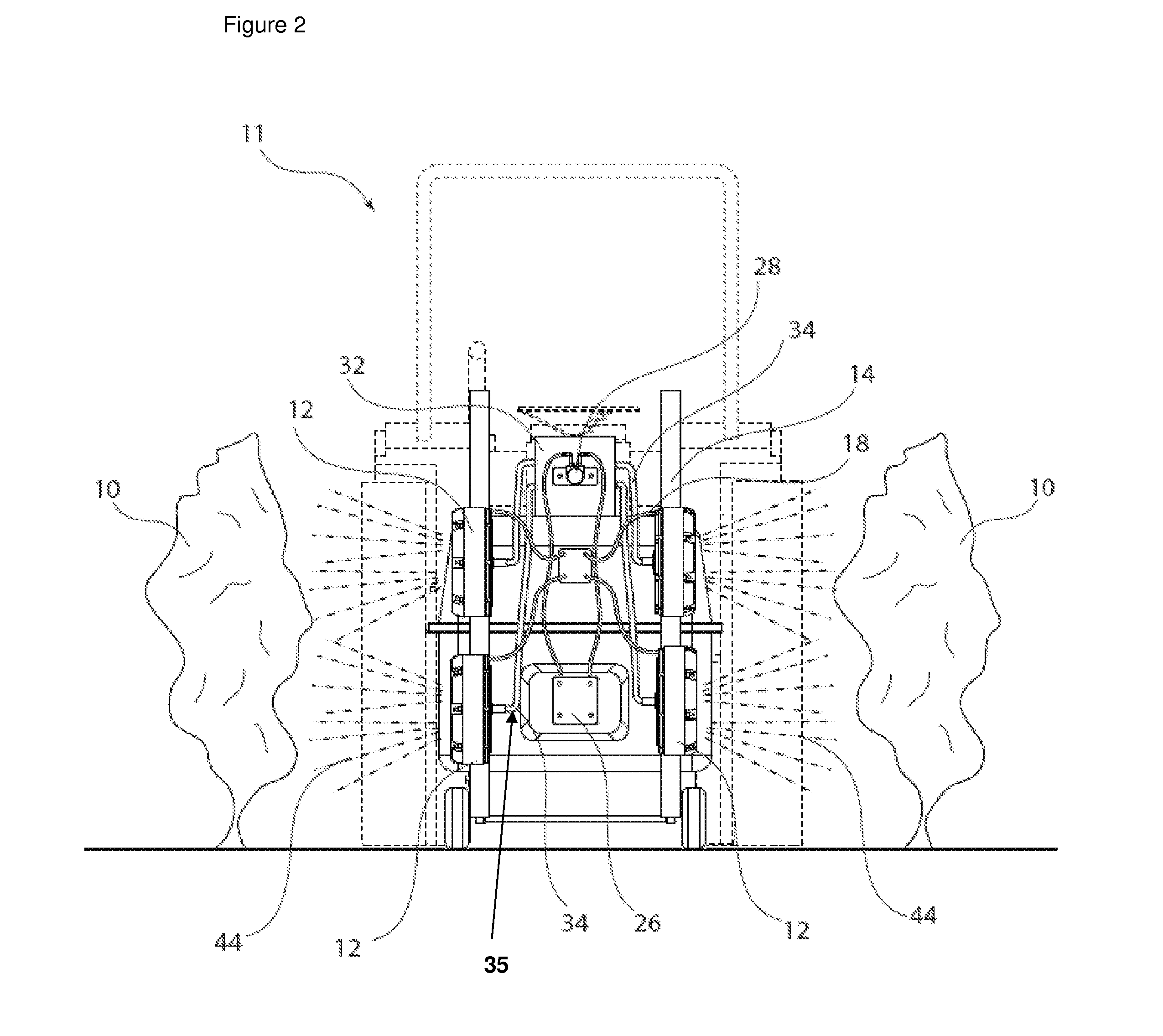
[0077]As shown in FIGS. 1 and 2, the mobile sprayer 11 includes fan units 12 attached to a frame 14. A reservoir 16, which includes liquid 17, is in fluid communication with fan units 12 via hoses 18. The frame 14 and the reservoir 16 are attached to a trailer 19, which is connected to a tractor...


PUM


Abstract

The present invention provides a drive system for a mobile blower or a mobile sprayer. The drive system includes at least one flexible cable drive which connects a fan unit of the mobile blower or the mobile sprayer to a rotary power source to drive the fan. The present invention also provides mobile blowers and mobile sprayers including the drive system.

Description

PRIORITY CLAIM[0001]This application claims priority to International Patent Application No. PCT / AU2010 / 000338, International Filing Date 24 Mar. 2010, entitled Drive System For A Mobile Sprayer And / Or For A Mobile Blower, and to Australian provisional patent application 2009901241, filed on 24 Mar. 2009, the contents of both of which are incorporated herein by reference in their entireties.FIELD OF THE INVENTION[0002]The present invention relates to a drive system for a mobile sprayer and / or for a mobile blower. The present invention also relates to a mobile blower for blowing an airstream onto plants and a mobile sprayer for spraying a substance onto plants.BACKGROUND OF THE INVENTION[0003]In the absence of perfect growing conditions (adequate water supply, nutrients and an nonexistence of pests), agricultural or horticultural grown plants require treatment by man. Such treatments may include, for example, removal of debris, fungal treatment, drying, watering, nutrient delivery or...

Claims


Application Information

Patent Timeline
12 Apr 2012
Publication
US20120085836A1
IPC
B05B9/06; F04B53/00
CPC
A01M9/003; A01M7/0014; B05B13/005; B05B13/02; B05B13/0278
Inventors
TIU, DAVID; DECK, BRENDAN