
Full authority fly-by-wire pedal system

a pedal system and full-authority technology, applied in the direction of actuating personally, mechanical equipment, transportation and packaging, etc., can solve the problems of frequent pedal movement, increased pilot workload, uncomfortable or otherwise distracting autopilot movement of the pedals, etc., to improve the yaw axis (azimuth) control of the aircraft, reduce pilot workload, and improve pilot workload. , the effect of reducing the workload of the pilo

Active Publication Date: 2010-01-12
SIKORSKY AIRCRAFT CORP
View PDF27 Cites 13 Cited by
  • Summary
  • Abstract
  • Description
  • Claims
  • Application Information

AI Technical Summary

Benefits of technology

The present invention provides a specialized pedal system for a Fly-By-Wire (FBW) flight control system that reduces the workload for the pilot and increases the aircraft's stability and coordination. The system includes a double gradient linkage assembly with a spring and damper system to provide a double gradient force feeling to the pedals. This allows for easier yaw axis control of the aircraft and reduces the amount of input required from the pilot. The system is compact and lightweight, simplifying the mechanical design and reducing parts count and complexity. Overall, the invention provides a more capable aircraft with a simplified and efficient pilot control system.

Problems solved by technology

This may significantly increase pilot workload.
When an autopilot is incorporated, the pedal position is synchronized to the autopilot which results in frequent movement of the pedals.
As the pedals are often utilized as footrests to stabilize the pilot, autopilot movement of the pedals may be uncomfortable or otherwise distracting.
Although significant benefits are realized with FBW flight control systems, conventional relatively large displacement FBW pedal systems have not utilized FBW flight control systems to full advantage as the pedal system remains essentially conventional.

Method used


Image

  • Full authority fly-by-wire pedal system
  • Full authority fly-by-wire pedal system
  • Full authority fly-by-wire pedal system

Examples


Embodiment Construction

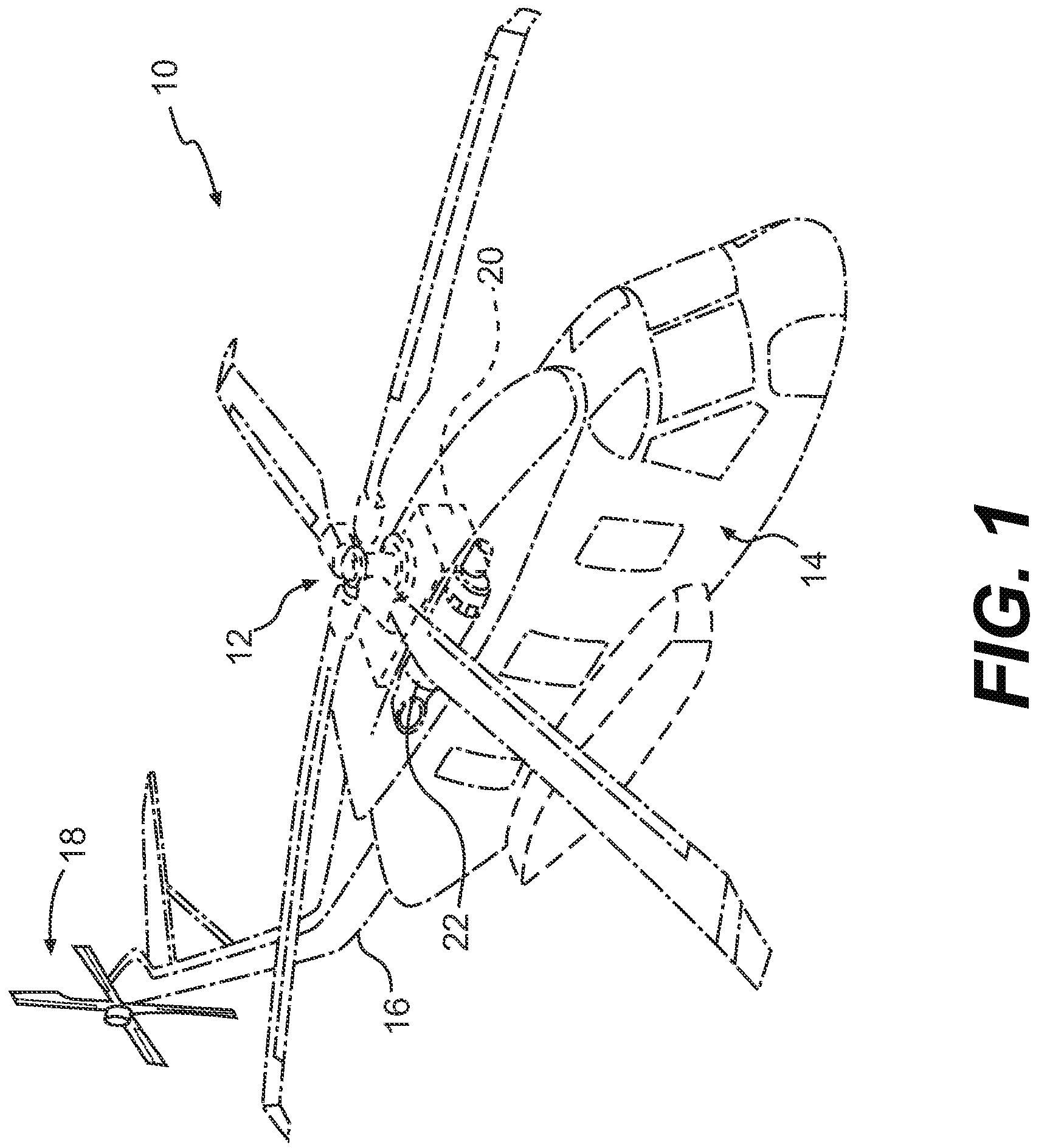
[0019]FIG. 1 schematically illustrates a rotary-wing aircraft 10 having a main rotor assembly 12. The aircraft 10 includes an airframe 14 having an extending tail 16 which mounts an anti-torque tail rotor system 18. The main rotor assembly 12 and the anti-torque tail rotor system 18 are driven through a transmission (illustrated schematically at 20) by one or more engines (illustrated schematically at 22). Although a particular helicopter configuration is illustrated in the disclosed embodiment, other anti-torque systems such as ducted fans and propulsors will also benefit from the present invention.

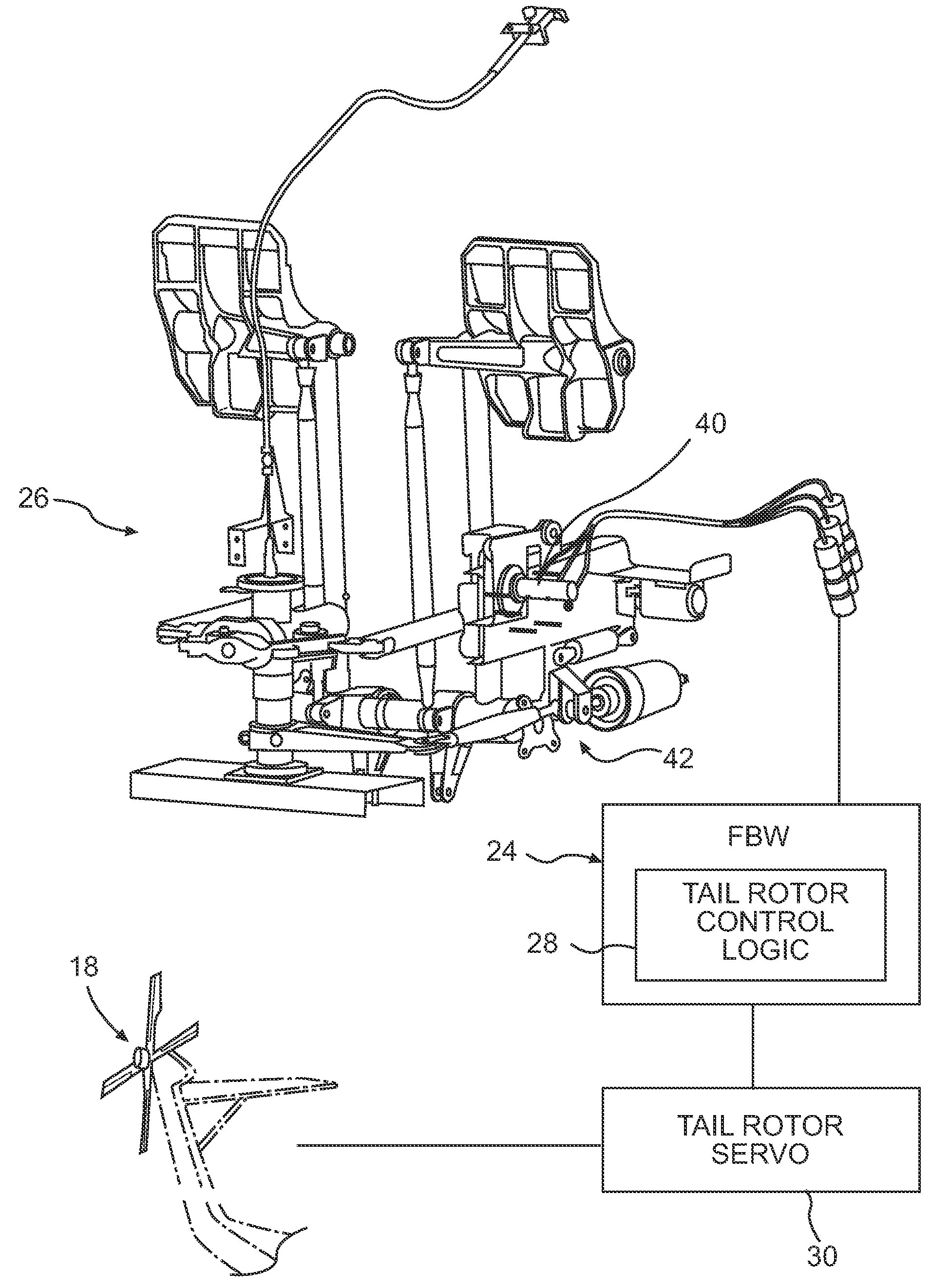
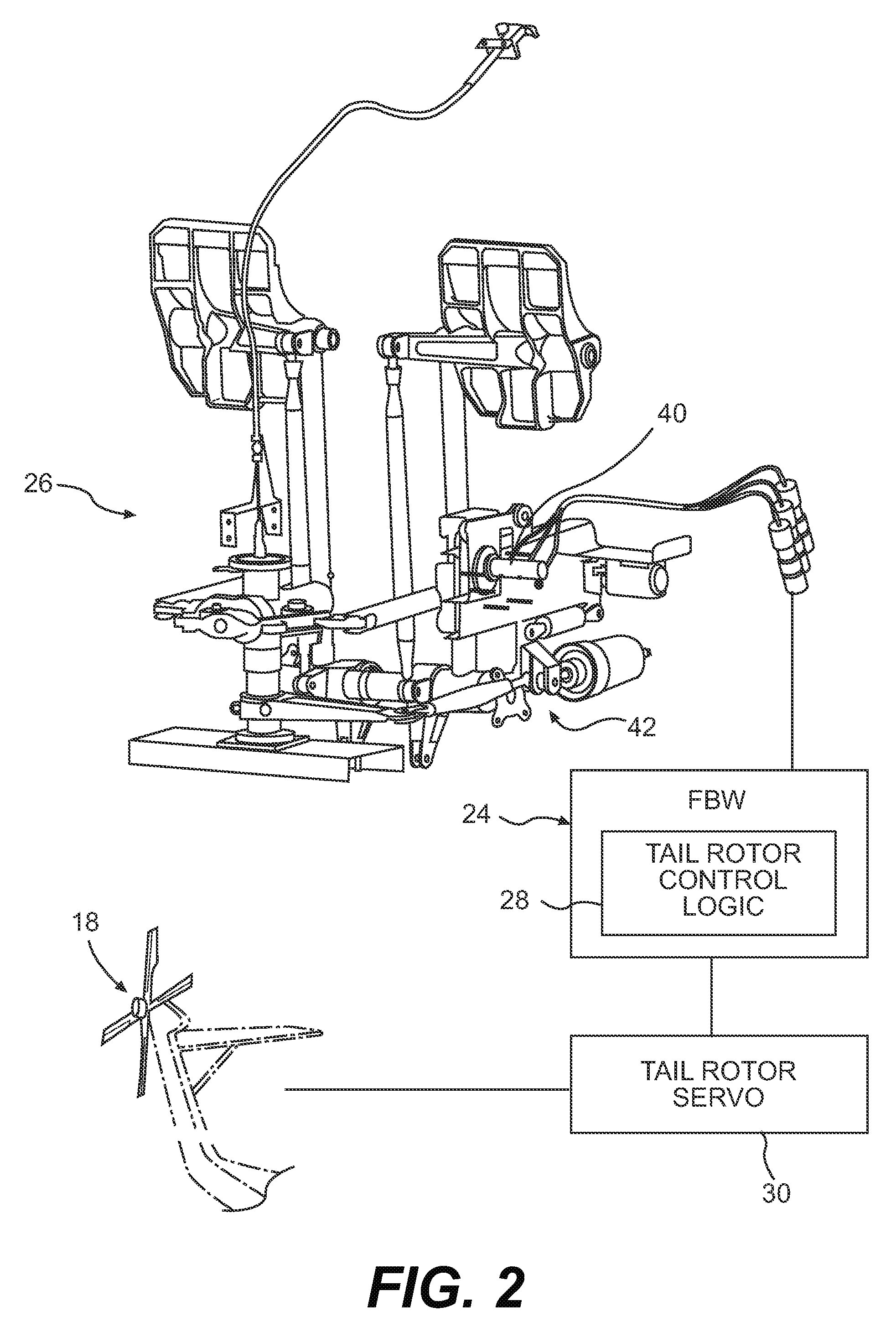
[0020]Referring to FIG. 2, the anti-torque tail rotor system 18 is driven through an aircraft flight control system 24. The aircraft flight control system 24 is preferably a full authority Fly-By-Wire (FBW) flight control system 24 that utilizes signals to convey pilot intentions to the flight control servos. In the FBW flight control system 24, a pilot provides input through FBW yaw fli...


PUM


Abstract

A pedal system particularly tailored to a Fly-By-Wire (FBW) flight control system includes a double gradient linkage assembly. The double gradient linkage assembly includes a damper system and a spring system that improves yaw axis (azimuth) control of the aircraft. Control is only required when a change in the yaw axis state is demanded. Since only minimal displacement inputs to such a FBW flight control system is required, the travel of the pedals are exceeding compact, such that pilot workload is significantly reduced through the reduction in the frequency and magnitude of aircraft control inputs.

Description

BACKGROUND OF THE INVENTION[0001]The present invention relates to an anti-torque tail rotor system, and more particularly to a small displacement pedal system for a full authority Fly-By-Wire (FBW) flight control system.[0002]The majority of helicopters utilize a single main rotor assembly and an anti-torque tail rotor assembly. The tail rotor assembly has proven to be efficient and reliable for providing lateral thrust to counteract induced torque generated by the main rotor assembly and to provide yaw directional control of the helicopter in hover, transitional, low, and high speed flight regimes.[0003]Control of the anti-torque tail rotor assembly is conventionally achieved through a relatively large displacement pedal system which provides control proportional to pedal displacement. The pilot must typically constantly manipulate the pedals to coordinate changes in power, bank angle or speed. This may significantly increase pilot workload.[0004]When an autopilot is incorporated, ...

Claims


Application Information

Patent Timeline
Patent Type & Authority Patents(United States)
IPC IPC(8): B64C19/02
CPCB64C13/04B64C13/503B64C27/56B64C27/68B64C27/78Y10T74/20888Y02T50/44Y10T74/20528Y10T74/209B64C13/044B64C13/507Y02T50/40
Inventor BOCZAR, BRUCESTILES, LORRENWITIAK, PETER T.
Owner SIKORSKY AIRCRAFT CORP
Learn More