Aircraft electrical network

a technology for electrical networks and aircraft, applied in the direction of transportation and packaging, sustainable transportation, power plant types, etc., can solve the problems of inefficiency in the electrical network, negating these advantages, power loss in electrical transmission, etc., to reduce electrical load, reduce current drawn, and reduce load

a technology for electrical networks and aircraft, applied in the direction of transportation and packaging, sustainable transportation, power plant types, etc., can solve the problems of inefficiency in the electrical network, negating these advantages, power loss in electrical transmission, etc., to reduce electrical load, reduce current drawn, and reduce load

US10131441B2Active Publication Date: 2018-11-20ROLLS ROYCE PLC

Image

  • Aircraft electrical network
  • Aircraft electrical network
  • Aircraft electrical network

Examples


Embodiment Construction

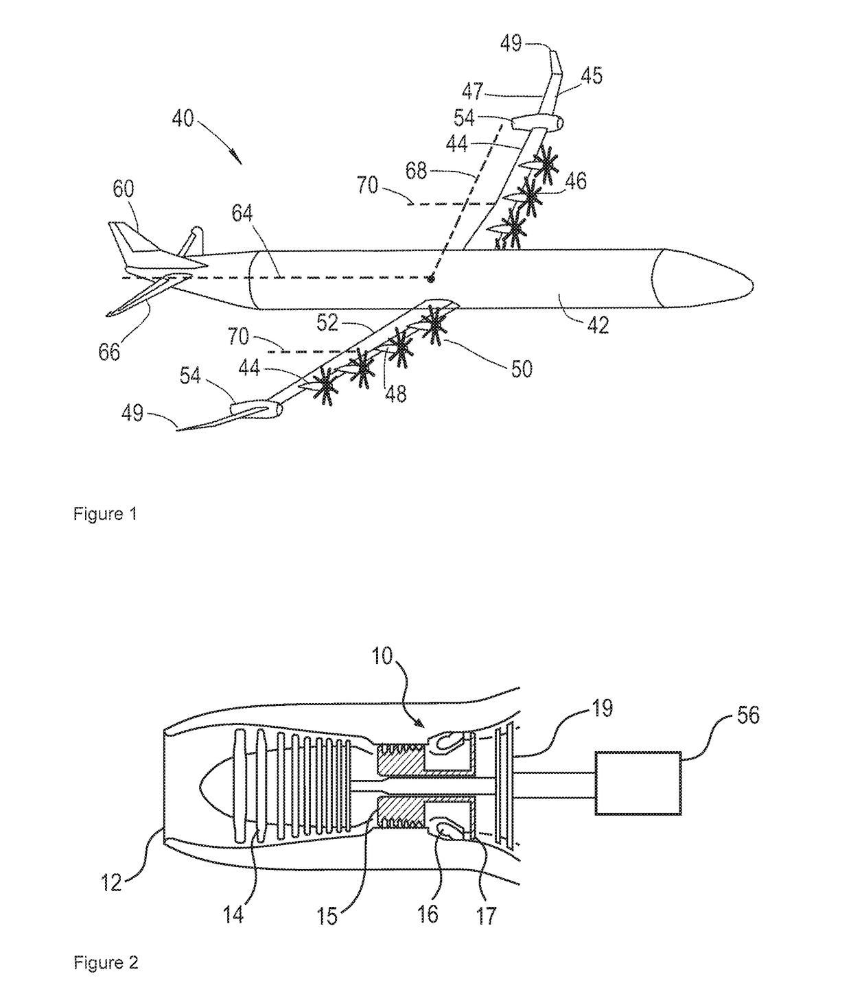
[0031]Referring to FIG. 1, a first aircraft 40 is shown. The aircraft comprises a fuselage 42, a pair of wings 44 extending therefrom generally normal to the fuselage 42, and an empennage located at an aft end of the fuselage 42. The empennage comprises vertical and horizontal tailplanes 60, 66.

[0032]A wingspan is defined by the distance between wing tips 49. Each wing 44 comprises a leading edge 45 and a trailing edge 47, which together define a chord extending therebetween. The ratio between the wingspan and chord length defines an aspect ratio. As can be seen from FIG. 1, the chord length varies along the wing span, from a relatively large chord at the wing root adjacent the fuselage 42, to a relatively small length at the wing tips 49. In cases such as this where the chord varies along the span, the aspect ratio AR can be defined as the square of the wingspan b divided by the area S of the wing planform:

[0033]AR=b2S

[0034]In the example shown in FIG. 1, the aspect ratio is approx...


PUM


Abstract

An electrical network for an aircraft. The aircraft includes at least one variable pitch propulsor. The electrical network includes a wound field synchronous AC electrical generator having a wound rotor driven by an internal combustion engine. The network further includes a voltage regulator configured to regulate output voltage of the electrical generator by regulating rotor winding magnetic field strength, and a synchronous AC drive motor coupled to a respective variable pitch propulsor and provided with power from the output of the electrical generator.

Description

FIELD OF THE INVENTION[0001]The present invention relates to an aircraft electrical network and a method of controlling the aircraft electrical network.BACKGROUND TO THE INVENTION[0002]Aircraft having electrical propulsors have been proposed, in which electrical power generated by a gas turbine engine driven electrical generator is used to power an electrical motor, which in turn drives a propulsor such as a fan or propeller to power the aircraft in flight. Studies such as “Distributed Turboelectric Propulsion for Hybrid Wing Body Aircraft” by Hyun Dae Kim, Gerald V Brown and James L Felder, published by the Royal Aeronautical Society, have shown that such systems may provide efficiency savings in some instances, as large numbers of propulsors can be used, which increases the overall efficiency of the aircraft. However, inefficiencies in the electrical network can in some cases negate these advantages. Such inefficiencies include the weight of the associated generators, power electr...

Claims


Application Information

Patent Timeline
20 Nov 2018
Publication
US10131441B2
IPC
B64D27/02; B64D35/02; B64D27/24
CPC
B64D27/02; B64D27/24; B64D35/02; Y02T50/64; B64D2221/00; Y02T50/44; B64D2027/026; Y02T50/40
Inventors
EDWARDS, HUW L.; SMITH, ALEXANDER C